
경주 천군동지역 단층에 기록된 제4기 지진성미끌림
초록
제4기 퇴적층을 절단하여 제4기 단층으로 인지되는 경우라도 그 단층을 따라 지진성미끌림이 발생했는지의 여부는 추가적으로 확인되어야 한다. 아울러 연구대상 단층이 제4기 이전부터 활동해온 것이라면 거기에서 관찰되는 지진성미끌림의 흔적은 제4기뿐 아니라 그 이전에 기록된 것일 수도 있다. 이번 연구에서는 단층에 남겨진 제4기 지진성미끌림의 기록을 확인하고자 경주시 천군동지역의 제4기 단층의 손상대 및 단층핵을 이루는 암석을 대상으로 물질분석 및 노두규모에서 미세규모까지의 구조분석을 실시하였다. 일차적으로, 손상대에서는 분쇄화강암이, 단층핵의 여러 위치에서는 단층비지의 주입세맥이 지진성미끌림과 관련된 기록임을 확인하였다. 이 중 동지진성 분쇄화작용으로 인한 분쇄화강암의 형성은 제4기 발생여부가 확실치 않은 반면, 단층비지 주입세맥의 경우 제4기 퇴적물을 포함한 것과 제4기 퇴적층 내로 주입한 것 등이 관찰되므로 제4기 지진성미끌림 발생을 분명하게 지시한다.
Abstract
A Quaternary fault may have slipped seismically or aseismically. If a Quaternary fault of interest has slipped since before the Quaternary, it should be examined whether any seismic slip indicator identified from it is directly related to the Quaternary slip or not. In this study, we conducted structural observation and material analysis on the damage zone and core of a Quaternary fault, Cheongun-dong area, Gyeongju, to find seismic slip records and determine whether they have originated from the Quaternary seismic slip. We recognized two geological features that may be directly related to seismic fault slip: pulverized granite in the damage zone and gouge injection veins in the core. Concerning the former, its formation timing is uncertain. The latter, some of which include the Quaternary sediment grains and are injected into the Quaternary deposit, reliably indicates the occurrence of the Quaternary seismic slip on the fault.
Keywords:
Quaternary fault, seismic slip, Cheongun-dong, principal slip zone, gouge injection vein키워드:
제4기 단층, 지진성미끌림, 천군동, 주미끌림대, 단층비지 주입세맥1. 서 론
제4기 단층활동에 대한 지질학적, 고지진학적 연구는 제4기 퇴적층을 절단하는 단층에 대한 상세한 야외조사를 기반으로 지진성미끌림의 발생 위치 및 시기, 재활주기, 지진규모의 평가 등을 목적으로 수행된다(Yeats et al., 1997; McCalpin, 2009; Kim, Y.-S. et al., 2020). 최근 양산단층 및 울산단층 등 한반도 동남부의 주요 단층대를 따라 제4기 미끌림을 경험한 단층들이 다수 확인되었고(Kim, Y.-S. et al., 2011; Kim, M.-C. et al., 2016; Cheon et al., 2020a), 이들의 활동시기는 단층비지 및 단층에 의해 변위된 퇴적물을 대상으로 한 여러 연대측정법(e.g., ESR, OSL, 14C)을 통해 제한되었다(Ree et al., 2003; Lee et al., 2015; Kim and Lee, 2020). 여기서 하나의 중요한 질문은 제4기 단층 연구에서 확인되는 단층미끌림이 모두 지진성미끌림인지, 그 단층에 대한 연대측정으로 제한된 활동시기가 모두 지진성미끌림의 발생시기를 의미하는지이다. 실제로, 지구조적으로 활동 중인 단층 중 느리고 안정적이며 지진을 동반하지 않는 미끌림(비지진성 미끌림 또는 포행; aseismic slip or creep)을 보이는 것들이 전세계적으로 다수 보고된다는 점(e.g., Harris, 2017)을 고려할 때 제4기 단층 연구에 있어 이 문제에 대한 논의가 필요하다.
그렇다면, 단층대에서 관찰되는 다양한 지질학적 특징 중 어떠한 것이 지진성미끌림을 지시하는가? 지표 근처의 낮은 수직응력(가령, <1 MPa) 하에서 퇴적물을 변위시키는 제4기 단층의 경우, 변위량이 예외적으로 크거나 미끌림속도가 매우 빠르지 않고서는 암석의 용융점에 도달할 만한 온도상승이 발생하지 않기 때문에(Han et al., 2014) 그러한 단층을 따라 슈도타킬라이트가 형성되는 것을 기대하기는 어렵다. 이보다는 주입세맥(injection vein), 즉 물을 포함하고 낮은 투수율을 갖는 단층암 내에서 마찰가열에 의한 일시적이고 급격한 온도상승과 그에 따른 과도한 유체압 증가에 의해 단층암 물질이 주변으로 주입되어 만들어지는 세맥(Lin, 2011; Rowe and Griffith, 2015)과 같은 구조가 제4기 단층에서 기대되는 지진성미끌림 지시자이다(e.g., Han et al., 2020).
한편, 국내에서는 아직까지 많이 연구된 바는 없으나(Park et al., 2020), 분쇄암(pulverized rock; Brune, 2001; Dor et al., 2006)도 지진성 단층운동을 지시할 수 있다. 분쇄암은 분쇄화작용(pulverization), 즉 지진성 단층파열과 관련하여 주로 결정질 암석(화성암 또는 변성암) 내부에 다수의 확장 미소단열이 형성되고 그에 따라 입자크기가 감소하는 프로세스에 의해 ‘응집력이 없이 마치 가루처럼 쉽게 부스러지는 상태를 갖게 된 암석’을 말하며, 전단미끌림의 도움 없이 만들어진다는 점에서 일반적인 단층비지와 성인적으로 다르다(Brune, 2001; Dor et al., 2006). 분쇄암은 대규모 활성단층(e.g., 미국의 San Andreas fault, 일본의 Arima-Takatsuki 구조선 등)에서 보고되었는데 단층핵이 아니라 그 주변의 손상대에서 비대칭적으로 발달하는 것이 일반적이다(Mitchell et al., 2011; Rempe et al., 2013). 분쇄암은 수많은 확장 미소단열의 발달이 특징적인 반면 전단변형의 영향은 크지 않기 때문에 암석의 일차적인 조직을 잘 유지한다(Dor et al., 2006; Mitchell et al., 2011; Fondriest et al., 2015; Sullivan and Peterson, 2017). 분쇄화작용은 지진성 단층파열(seismic fault rupture)시 파열 전면부(rupture fronts)에서 일시적으로 발생하는 높은 응력변형률(strain rate)의 변형과 관련된 것으로 생각되며(Doan and Gary, 2009; Yuan et al., 2011; Rowe and Griffith, 2015; Aben et al., 2016), 단층을 경계로 접하는 두 암체의 강성률(stiffness) 및 그에 따른 탄성파 속도(seismic velocity) 차이 등이 비대칭적인 분쇄암 분포와 관련된 것으로 추정되었다(Mitchell et al., 2011).
아울러, 단층 미끌림이 극도로 국지화된 영역인 주미끌림대(principal slip zone; PSZ)의 경우 지진성미끌림을 모의하는 고속전단시험 뿐 아니라 고착-미끌림(stick-slip)을 보이는 저속전단시험에서도 잘 나타나므로 주목할 필요가 있다(Boutareaud et al., 2008; Brantut et al., 2008; Yao et al., 2013; Aretusini et al., 2019; Han et al., 2020). 이 구조의 경우 그것을 구성하는 물질의 강성(stiffness)이 주변암의 그것보다 큰 경우에만 지진성미끌림을 보이므로 지진성미끌림의 ‘잠재적’ 발생 가능영역으로 고려할 수 있다(Ikari, 2015).
한편, 하나의 제4기 단층에서도 위치별로 접촉하는 암체(또는 퇴적물)가 달라짐에 따라(e.g., Heynekamp et al., 1999) 각 위치에서 관찰되는 구조, 그 구조의 형성시기, 변형특성 등이 서로 다를 수 있다(e.g., Park et al., 2020). 이 경우 제4기 단층의 여러 위치에서 지진성미끌림의 흔적이 관찰된다 해도 그것들이 모두 제4기 미끌림과 관련된 것은 아닐 수 있으므로 주의를 요한다.
본 연구는 하나의 노두에서 제4기 단층 상의 위치별로 구조와 물질이 어떠한 차이를 보이는지를 이해하고 거기에 기록된 제4기 지진성미끌림의 흔적을 식별하는 것을 목표로 수행되었으며, 이를 위해 경주 천군동지역의 제4기 단층을 대상으로 노두규모 구조관찰에서부터 암판규모(rock-slab scale) 단층암 구조관찰을 거쳐 미세규모 물질분석 및 구조관찰까지 실시하였다. 이 논문에서는 그 단층의 손상대와 단층핵의 여러 위치에서 관찰되는 주요 구조들과 물질적 특성을 보고하고, 이들 중 어떠한 특징들이 제4기 지진성미끌림을 지시하는지에 대해 논의한다.
2. 천군동지역 제4기 단층
연구지역은 과거로부터 울산단층의 곡부로 알려진 곳의 인근에 위치한다(그림 1a, 1b). 여기에는 백악기 퇴적암인 흑색셰일과 이들을 관입한 백악기 흑운모화강암, 각섬석화강암, 우흑질(melanocratic) 각섬석섬록암이 나타나며, 이들은 제4기 사력질 퇴적물에 의해 부정합적으로 피복되어 있다(그림 1c). 연구대상 단층이 위치한 지점은 경주시 천군동 택지조성 부지에서 행정안전부 ‘한반도 단층구조선의 조사 및 평가기술개발’ 과제의 일환으로 2018년에 수행된 굴착조사 시 제4기 단층운동이 확인된 네 곳 중 하나로, Kang (2019)에 의해 천군동2지점(N 35° 49′ 05.1″, E 129° 17′ 10.5″)으로 기재된 것이다(그림 1c). 앞으로 본문에서 간략히 주단층으로 언급되는 것은 바로 이 단층을 의미한다. 다만, 천군동2지점에서 관찰만으로는 불확실한 점이 있어 동일한 단층의 자취에 위치하는 천군동1지점의 일부 영역를 추가적으로 관찰하였다.
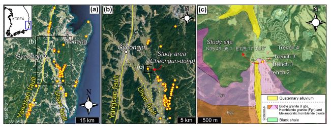
(a) Locations of Quaternary faults (solid yellow circles) along the Yangsan and Ulsan faults in SE Korea (modified from Kim, C.-M. et al., 2020). (b) Close-up view of the boxed area in (a), where our study area is located. (c) Geological map of the study area (modified from Tateiwa, 1924). Fieldwork in this study was mainly conducted on the fault exposed at the Cheongun-dong trench site 2 (N35° 49' 05.1" E129° 17' 10.5").
천군동지역의 네 굴착지점(trench 1-4; 그림 1c)에서 확인된 제4기 단층들은 하반에서 제4기 퇴적층, 상반에서는 기반암을 보이는 것들이다(Kang, 2019). 천군동3지점의 제4기 퇴적층에 대한 OSL 및 14C 연대측정을 통해 추정한 최후기 단층운동시기는 <106±8 ka이다(Jeong et al., 2018). 기존 연구에서 보고된 천군동1-4지점의 단층면의 자세는 N12°-20°E/70°-80°SE, 단층조선의 선주각(rake)은 7°-26°N으로, 역이동성 성분보다 우수향 주향이동 성분이 우세한 사교이동단층을 지시하는데, 이는 대자율이방성에 기반한 운동학적 분석결과와 잘 부합한다(Kang, 2019).
천군동2지점의 기반암은 다수의 고철질암맥(mafic dyke)을 포함하는 각섬석화강암이며 단층을 경계로 기반암이 제4기 퇴적층 위에 놓인다(그림 2a, 2b). 본 연구에서 측정된 단층(주단층)의 자세는 N17°-22°E/84°-87°SE, 단층면의 한 지점에서 관찰된 단층조선의 선주각은 55°N이다(그림 2a). 이는 기존 연구결과(Kang, 2019)와 비교할 때 단층면 자세는 유사하나 선주각에서는 다소 차이를 보이는 것으로, 하나의 단층에서도 위치별로 조선의 자세가 다르거나, 휘어진 조선, 복수의 조선이 나타날 수도 있다는 점을 고려할 때(e.g., Otsuki et al., 1997), 단층의 특정 지점에서의 국지적인 자세로 보는 것이 타당해 보인다. 연구지점에서 확인되는 운동감각은 우수향-역단층성 사교이동이며, 단층의 겉보기 변위는 대략 2 m이다(그림 2a).
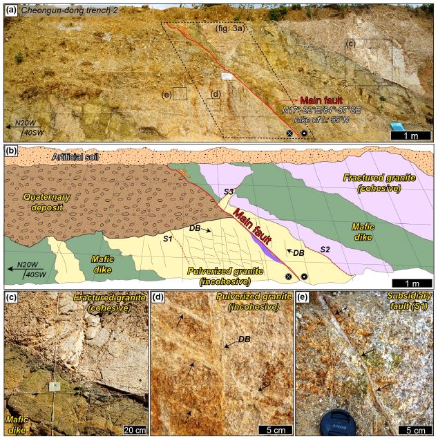
(a) Overview photo of the study site (Cheongun-dong trench 2). There is a main fault in the center (red line). The attitudes of the fault surface (S) and the rake of striation (L) on it are N17-22°E/84-87°SE and 55N, respectively. (b) Schematic illustration of (a). DB, deformation band; S1-S3, subsidiary faults. (c) Fractured granite and mafic dike in the hanging wall. The former is cohesive, although it looks highly fractured. (d) Pulverized granite, which is densely fractured and easily disaggregated into fine particles by hand (incohesive). Note the occurrence of deformation bands (DBs, black arrows) in the rock. (e) Fault gouge (black arrows) in S1, located at 3 m from the main fault.
현장에서 관찰되는 화강암은 단열화강암(fractured granite)과 분쇄화강암(pulverized granite)으로 구분된다(그림 2b). 백색 내지 옅은 분홍색의 단열화강암은 응집력을 가지고 있고 망치로 타격 시 단열을 따라 갈라진다(그림 2c). 반면에 분쇄화강암은 대체로 옅은 분홍색을 띠나 일부 적색으로 보이는 부분을 포함하며, 그 내부에 단열보다는 다수의 변형띠(deformation band)가 나타나고(그림 2d) 응집력이 미약하여 손으로도 쉽게 부스러진다. 단층 하반의 화강암은 관찰가능영역 전체에서 분쇄화강암으로 나타나는 반면, 상반의 화강암은 단층에서부터 약 1 m 이내에서는 분쇄화강암으로 나타나다가 하나의 부차단층(세 개의 부차단층 S1-S3 중 S2를 의미)을 경계로 점진적으로 단열화강암의 모습을 보인다(그림 2b). 분쇄화강암 내 변형띠는 주변 물질에 비해 더 밝은 색을 띠며, 그것의 밀도(출현빈도)는 상반보다는 하반에서, 그리고 단층과 가까울수록 더 높다(그림 2b). 대표적인 변형띠의 자세는 저각인 것은 N36°E/46°SE, 고각인 것은 N54°E/83°SE이다(그림 2d; 검정 화살표). 화강암을 관입한 고철질암맥은 노두의 여러 위치에서 나타나는데 단층의 일부에서 제4기 퇴적층과 직접 접촉하기도 한다(그림 2b). 이 고철질암맥은 황색 또는 녹색을 띠며, 손으로도 쉽게 부스러질 만큼 풍화 정도가 심하다(그림 2c). 주단층 주변으로 나타나는 세 개의 부차단층 중(그림 2b; S1-S3), 부차단층1(S1)과 부차단층2(S2)의 자세는 각각 N18°E/84°SE와 N25°E/80°SE로, 주단층의 자세와 유사하나, 부차단층3(S3)의 자세는 N65°W/40°NE로 주단층과 큰 차이를 보인다(그림 2b). S1에서는 약 0.5 cm 폭의 백색 단층비지가 나타나며(그림 2e), S2와 S3에서는 단층비지가 확인되지 않는다.
본 연구에서는 주단층을 따라 하부에서 상부로 가며 서로 다른 네 위치, 즉 분쇄화강암 내부에 단층이 발달하는 곳(1번 위치), 분쇄화강암과 제4기 퇴적층이 접하는 곳(2번 위치), 그리고 고철질암맥과 제4기 퇴적층이 접하는 두 곳(3-1번, 3-2번 위치)에서 단층의 구조 및 물질에 대해 조사하였다(그림 3a). 1번 위치에서는 약 0.5 cm 폭의 갈색 단층비지와 함께 모암인 분쇄화강암이 심하게 파쇄되어 만들어진 단층암이 나타나며(그림 3b), 거기서 단층조선이 확인되었다. 2번 위치에서는 약 0.5 cm 폭의 갈색 단층비지가 나타나며, 그 물질이 상반(분쇄화강암)쪽으로 주입된 모습이 확인되었다(그림 3c). 하반의 제4기 퇴적층에서는 파쇄변형의 흔적은 인지되지 않았다(그림 3c). 3-1번 위치에서는 제4기 퇴적층과 고철질암맥의 경계가 분명하게 정의되지 않으며 단층비지 또한 잘 관찰되지 않는다(그림 3d). 3-2번 위치에서는 그 경계가 잘 인지되며, 약 0.5 cm 폭의 단층비지와 그것이 상반(고철질암맥)쪽으로 주입된 구조가 관찰되었다(그림 3e). 3-2번 위치의 경우 천군동2지점과 단지 수 m 떨어진 천군동1지점(그림 1c)의 일부 영역으로, 천군동2지점의 3-1번 위치에 대응되는 곳이다.
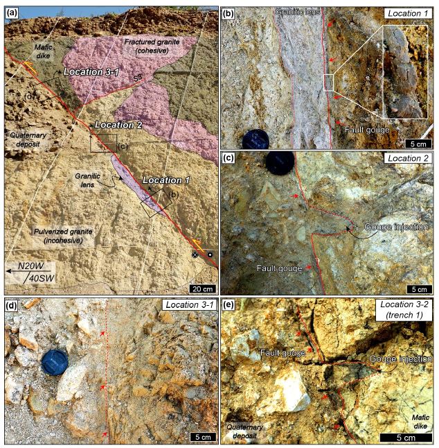
(a) Photograph of the main fault (solid red line). The boxed areas display the sampling locations for material analysis and structural observation. (b) Close-up view of Location 1. The red arrows indicate the fault gouge. The inset shows part of the gouge, which feels sticky. (c) At Location 2, an injection of the fault gouge into the hanging wall (pulverized granite) is observed. (d) At Location 3-1, the Quaternary deposit has the fault contact with the mafic dike. Any fault gouge is hardly found here. (e) At Location 3-2, which is situated in Trench 1 next to Trench 2, the main fault in Trench 2 is continued (see Fig. 1c for the location). An injection of the fault gouge (red dashed line) into the hanging wall (mafic dike) is observed along the fault.
3. 구조 및 물질분석 방법
노두규모 관찰 후 모암에서는 비정향 벌크시료를, 단층의 네 위치에서는 정향된 단층암 벌크시료를 획득하였다. 실내에서 하루 이상 실온 건조 후 벌크시료의 겉면은 저점도 에폭시를 이용하여 보강하였다. 이후, 단층암 구조 관찰용 시료는 단층면에 수직하고 단층조선에 나란하게 절단하였고 단층비지 주입구조 관찰용 시료는 노두면의 자세대로 절단하였다. 절단된 시료는 다시 실온에서 하루 이상 건조한 후 저점도 에폭시를 이용해 추가적으로 보강하였다. 암판(rock-slab) 및 박편 제작을 위한 연마과정에서는 수분에 의한 시료의 훼손을 최대한 방지하기 위해 연마제를 섞은 방전가공유를 이용하였다. 스캐닝을 통해 암판 및 박편시료의 고해상도(1200 dpi) 이미지를 얻어내고 이를 구조분석에 이용하였다.
암석 조직 및 변형 미구조에 대한 기본적인 관찰은 광학현미경(Olympus BX53)을 통해 실시하였으며, 보다 작은 규모의 상세 관찰에는 경상국립대학교 공동실험실습관의 에너지분산형 분광분석기(energy dispersive X-ray spectroscopy; EDS; Oxford X-Max 50)가 장착된 전계방사 전자현미분석기(field emission electron probe micro-analyzer; FE-EPMA; JEOL JXA-8530F PLUS)를 사용하였다. 분석조건은 가속전압 15 kV, 빔 전류 10 nA이다. 암판규모에서 분대한 단층암 세부영역의 광물조성은 분말시료의 X선 회절분석을 통해 확인하였다. 분말시료는 암판의 서로 다른 위치에서 마이크로드릴(micro-drill; FBS 240/E, Proxxon)로 긁어낸 물질을 아게이트에서 10분동안 분쇄함으로써 준비하였다(Kim, C.-M. et al., 2017). 제4기 퇴적물의 분말시료의 경우, 퇴적물 내 역에 의한 영향을 최소화 하고자 체를 이용하여 얻어낸 125 μm 미만의 물질로부터 준비하였다. 분말시료는 이후 약 24시간동안 50°C의 오븐에서 건조시켰다. 분석은 경상국립대학교 공동실험실습관의 X선 회절분석기(XRD; Bruker D8 Advance A25)를 사용하였으며, 40 kV, 40 mA, 70° (2θ) 구간, 주사간격 0.02°, 스텝당 주사시간 0.2 s, 니켈필터를 이용한 구리 파장의 X선 조건으로 실시하였다. 회절실험결과의 정성분석에는 Bruker AXS Diffrac Eva 프로그램을 이용하였다.
4. 단층손상대 암석
4.1 암판규모 구조 및 광물조성
단열화강암(FRG)에는 다수의 암판규모(~10 cm 내외의 암판크기 정도의 중규모) 단열이 발달하는데 그 대부분은 전단 변위가 미약하거나 없는 확장단열이다(그림 4a). 한편, 분쇄화강암(PG)에서는 그러한 단열은 거의 관찰되지 않으며 다수의 변형띠가 발달한다(그림 4b). 변형띠 내부는 그 외부에 비해 밝게 보이고 낮은 경사각의 변형띠와 높은 경사각의 변형띠가 서로 교차하며, 일부 변형띠의 경계부를 따라서는 붉게 착색된 모습이 관찰된다(그림 4b). 고철질암맥(MD)은 세립질 입자들로 구성되고 다수의 단열이 발달하며 단열 내부는 붉은색 또는 검은 물질이 채우고 있다(그림 4c). 부차단층1(S1)은 약 3-4 cm 폭의 단층핵을 가지는데, 이는 약 0.5 cm 폭의 백색 점토질 단층비지와 그 주변의 단층각력암으로 구성된다(그림 4d). 단층핵 주변으로는 PG가 나타난다(그림 4d).
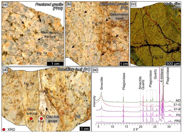
Rock slab images and powder X-ray diffraction patterns of the rocks in the damage zone. (a) Mesoscopic fractures (black arrows) in the fractured granite (FRG). (b) About 0.3 cm thick deformation bands (black arrows) in the pulverized granite (PG). (c) Fine-grained mafic dike (MD). (d) About 0.5 cm thick clay-rich gouge (S1-G) and 3-4 cm thick micro-breccia (S1-B) in S1. (e) Powder X-ray diffraction patterns of the rocks (FRG, PG, and MD) in the damage zone and the fault rocks (S1-G and S1-B). The sampling locations of S1-G and S1-B are indicated by the solid red circles in (d).
FRG와 PG는 대부분 석영, 장석 그리고 소량의 스멕타이트로 구성되며, 광물조성에서는 큰 차이를 보이지 않는다(그림 4e). S1의 단층각력암(S1-B)은 모암에 비해 스멕타이트 피크가 다소 높고, 점토질 단층비지(S1-G)의 경우 모암에 비해 스멕타이트 피크가 크게 높다(그림 4e). MD는 대부분 사장석과 스멕타이트로 구성되며 석영의 결핍이 특징적이다(그림 4e).
4.2 미구조
FRG는 1-2 mm 크기의 석영과 장석 입자들로 구성되며, 다양한 길이의 입자간단열(intergranular fractures)을 보인다(그림 5a). PG 또한 주로 약 1-2 mm 크기의 석영과 장석 입자들로 구성되나, 입자 내부에 많은 미소단열(microfracture)이 발달하여 하나의 큰 입자가 약 100-200 μm 크기의 다수의 작은 입자들로 분리되어 있다(그림 5b). 위치에 따라 미소단열밀도는 매우 불균질하여 수십 μm 미만의 크기의 입자들로 파쇄된 경우도 관찰된다(그림 5b). PG는 화강암의 일차적인 암석조직을 대체로 유지하고 있고, 미소단열들은 대부분 열린 상태로 나타나며 장석의 벽개를 따라 발달하는 것들을 제외하고는 우세한 발달 방향을 보이지는 않는다(그림 5b). PG 내에서 변형띠는 대체로 약 0.5-1 mm 폭으로 나타나며, 구성물질 중 암편은 최대 0.3 mm 크기이고 기질부는 보다 작은 크기의 미세입자들로 구성된다(그림 5c, 적색 점선 안쪽). 변형띠 주변의 일부 미소단열들은 판상광물 또는 불투명광물로 채워져 있다(그림 5c).
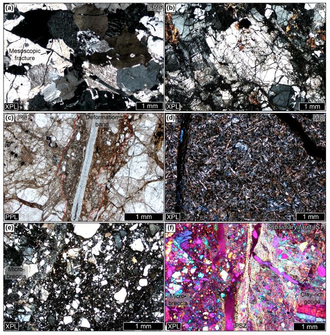
Photomicrographs of the rocks in the damage zone. (a) Fractured granite (FRG), where a few mesoscopic fractures are observed. (b) Pulverized granite (PG) preserving primary granitic texture despite extensive microfracturing. (c) Deformation band in the PG. It is ~1 mm thick and contains much smaller grains than the PG. (d) Mafic dyke (MD). (e) Micro-breccia in S1. (f) The boundary area between the micro-breccia and clay-rich gouge of S1, where a ~300 μm thick PSZ occurs (gypsum plate inserted). XPL, crossed-polarized light; PPL, plane-polarized light.
MD는 장축이 약 0.1-0.3 mm인 주상의 사장석 입자, 점토광물 및 불투명광물로 구성된다(그림 5d). S1의 단층각력암은 육안으로는 암편이 잘 관찰되지 않는 미소각력암(micro-breccia)이며(그림 4d), 그 내부는 최대 1 mm 크기의 암편과 미세 파쇄입자들로 구성된다(그림 5e). S1의 단층비지는 주변의 미소각력암에 비해 암편의 양이 적고 크기는 작으며 기질부는 주로 강한 정향배열을 보이는 점토광물로 이루어져있다(그림 5f). S1의 각력암과 단층비지의 경계에서는 점토광물의 강한 정향배열을 보이는 주미끌림대(principal slip zone; PSZ)가 나타난다(그림 5f). 그것은 약 100-300 μm 폭의 구조로서, 주변 물질에 비해 암편의 함량이 매우 적고 대부분 점토광물로 채워져 있다(그림 5f).
5. 단층암
5.1 암판규모 구조 및 광물조성
단층의 서로 다른 네 곳에서 단층암 구조 관찰용 시료 3개(1번, 2번 및 3-1번 위치; 그림 6a, 6c, 6e)와 단층비지 주입구조 관찰용 시료 2개(2번 및 3-2번 위치; 그림 6g, 6h)등 총 5개의 암판을 제작하여 분석하였다.
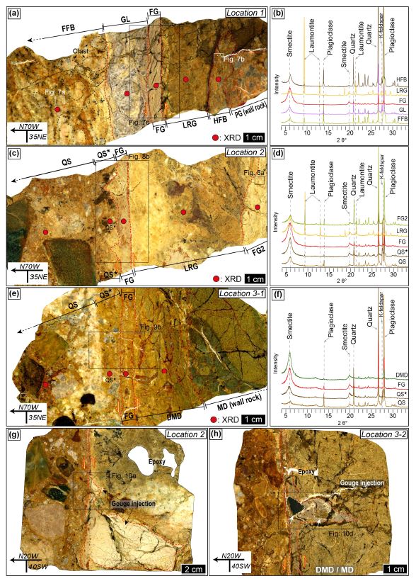
(a), (c), (e) Slab images of the fault rocks and their neighbors at Locations 1 to 3. (b), (d), (f) Powder X-ray diffraction patterns of the rocks shown in (a), (c), and (e). The sampling locations for the XRD analyses are indicated by the solid red circles. (g), (h) Slab images showing fault gouge injections at Locations 2 and 3-2, respectively. FFB, footwall fault breccia; GL, granitic lens; FG, fault gouge; LRG, laumontite-rich gouge; HFB, hanging wall fault breccia; PG, pulverized granite; QS, Quaternary sediments; QS★, Quaternary sediments about 1 cm away from the fault; DMD, deformed mafic dike; MD, mafic dike.
1번 위치의 단층암은 서편에서 동편으로 가며 하반 단층각력암(footwall fault breccia; FFB), 화강암질 렌즈(granitic lens; GL), 단층비지(fault gouge; FG), 로몬타이트가 풍부한 단층비지(laumontite-rich gouge; LRG), 상반 단층각력암(hanging wall fault breccia; HFB) 등 총 5개의 영역으로 구분된다(그림 6a). FFB는 대략 5 cm 폭으로 나타나는데 모암과의 경계는 명확하기보다는 점이적이다. 이것의 암편들은 수 cm 크기여서 육안으로 확인이 가능하며 분홍색 내지 갈색을 띠는 기질물질에 의해 둘러싸여 있다(그림 6a). GL은 암판에서 약 2 cm 폭의 영역이며 보라색, 백색 및 갈색의 점토질 기질물질 및 0.5 cm 이하 크기의 암편들로 구성된다(그림 6a). FG는 갈색의 점토질 물질이며 약 0.5 cm 폭으로 나타난다. 주변 물질보다 암편의 함량이 훨씬 적으며 P-전단 방향의 엽리를 보인다(그림 6a). LRG는 짙은 갈색을 띠며 약 2-3 cm 폭으로 나타난다. 이 영역은 육안으로 식별 불가능한 세립질 입자들로 구성되어 있고, FG와 인접한 곳에서 더 밝은 색을 띤다(그림 6a). HFB는 짙은 갈색의 물질로, 약 1 cm 폭으로 나타난다(그림 6a). 그것은 인접하는 PG에 비해 입자크기가 작고 분쇄암조직을 보이지 않는다.
1번 위치에서 분대된 단층암들을 대상으로 X선 회절분석을 실시하였다. FFB, GL, FG 및 HFB는 주로 석영, 장석 및 스멕타이트로 구성되며, 그 중 FFB와 HFB는 소량의 로몬타이트를 포함한다(그림 6b). FG는 스멕타이트 피크가 가장 높고 석영과 장석 피크는 낮다. LRG는 로몬타이트 피크가 높고 주변 단층암에 비해 스멕타이트 피크가 낮으며 석영과 장석의 결핍이 특징적이다(그림 6b).
2번 위치 단층암 암판에서 서편에는 제4기 퇴적물(Quaternary sediments; QS)이 존재하는데, FG에 바로 인접한 영역과 그렇지 않은 영역의 구조 및 물질적 차이를 확인하기 위해, QS 중 FG로부터 1 cm 이내의 영역을 QS★로 따로 구분하였다. FG의 동편으로는 LRG와 또 다른 단층비지(FG2) 순으로 나타난다(그림 6c).
QS는 수 cm 크기의 역들을 다량 포함하며 기질부는 적갈색의 사력질 퇴적물로 구성된다. QS와 QS★ 모두에서 뚜렷한 변형구조는 관찰되지 않는다(그림 6c). FG는 갈색을 띠는 점토질 물질이며 약 0.5-1 cm 폭으로 나타난다. FG 내부에서는 주변의 암석에 비해 암편의 함량이 적고, P-전단 방향의 엽리가 약하게 발달한다(그림 6c). LRG는 약 4-5 cm 폭으로 나타나며, 1 cm 이하 크기의 암편들과 세립질 기질부로 구성된다. 이 영역은 노란색과 짙은 갈색 물질이 불규칙적으로 교호하는데, FG에 인접한 부분은 노란색으로 FG2에 인접한 부분은 짙은 갈색으로 나타난다(그림 6c). FG2는 약 1 cm 폭의 백색에 가까운 밝은 색의 점토질 물질이다(그림 6c).
2번 위치의 영역별 X선 회절분석 결과는 다음과 같다. QS 및 QS★의 기질부는 석영, 장석 및 스멕타이트로 주로 구성되며, QS보다 QS★에서 장석 피크가 낮고 스멕타이트 피크는 더 높다. FG 또한 석영, 장석 및 스멕타이트로 구성되며, 2번 위치 물질 중 스멕타이트 피크가 가장 높다. LRG는 로몬타이트와 스멕타이트로 구성되고 석영과 장석은 결핍되어 있다. FG2는 석영, 장석, 스멕타이트 및 로몬타이트를 모두 포함한다(그림 6d).
3-1번 위치의 QS에서도 FG에 바로 인접한 영역과 그렇지 않은 영역의 구조 및 물질적 차이를 확인하기 위해 2번 위치에서처럼 FG로부터 1 cm 이내의 영역을 QS★로 따로 구분하였다. FG의 동편으로는 변형된 고철질암맥(deformed mafic dike; DMD)과 그렇지 않은 고철질암맥(MD)이 나타난다(그림 6e).
이 위치의 QS에는 수 cm 크기의 역들이 다량 포함되어 있고, 기질부는 적갈색의 사력질 퇴적물로 구성되며, 백색으로 보이는 물질이 단층과 나란한 자세로 나타난다(그림 6e). FG에 인접한 QS★에서는 QS에 비해 역의 함량은 적고 역의 크기도 작다(그림 6e). 3-1번 위치의 FG는 적갈색을 띠며 약 0.5 cm 폭으로 나타난다. 1, 2번 위치의 FG에 비해 암편의 함량은 더 높으며 P-전단 방향의 엽리는 관찰되지 않는다(그림 6e). DMD는 변형되어 MD의 조직을 잃어버린 상태의 물질로서, 약 3 cm 폭으로 나타나며, 녹색을 띠는 1-2 cm 크기의 암편들과 그 사이를 채우는 갈색 점토질 물질로 구성된다(그림 6e).
3-1번 위치의 영역별 X선 회절분석 결과, QS 및 QS★의 기질부 그리고 FG는 주로 석영, 장석 및 스멕타이트로 구성되며, QS에서 FG로 갈수록 스멕타이트 피크가 더 높아진다. DMD는 주로 스멕타이트와 장석으로 구성되며, 전체 분석영역 중 스멕타이트 피크가 가장 높고 석영이 결핍된 것이 특징적이다(그림 6f).
노두에서 주입구조가 확인된 두 위치(2번 위치 및 3-2번 위치)에서 각각 하나씩 암판을 제작하여 관찰하였다. 2번 위치의 암판에서는 백색의 단층비지가 하부에서는 약 2 cm 이상의 폭으로, 그보다 상부에서는 약 0.5 cm 폭으로 상반(PG)쪽으로 주입되어 있다. 주입된 단층비지는 암편의 함량이 매우 적으며 대부분 점토질 물질로 이루어져 있다(그림 6g). 3-2번 위치에서는 회색을 띠는 단층비지가 상반(DMD 및 MD)쪽으로 주입되어 있는데, 그 폭은 약 1 cm 내외이고 그 내부에 녹색의 MD 암편과 검은색의 QS 암편 등을 포함한다(그림 6h; 흰색 화살표).
5.2 미구조
FFB는 PG의 조직을 유지하고 있는 수 mm 크기의 암편 및 1 mm 이하 크기의 파쇄된 석영과 장석 입자들로 구성된다(그림 7a). HFB는 최대 1 mm 크기의 암편들과 기질부의 파쇄입자 및 점토광물로 구성된다(그림 7b). FFB에서는 점토광물의 정향배열이 잘 관찰되지 않는 반면, HFB에서는 정향배열이 강하게 나타나며, HFB는 FFB에 비해 암편의 양이 적고, 크기도 더 작다(그림 7a, 7b). FG와 그 주변의 GL, LRG를 포함하는 박편에서, GL과 FG의 경계는 완만한 물결 모양으로 나타나며, FG와 LRG의 경계는 상대적으로 더 날카롭고 직선적으로 나타난다(그림 7c). LRG는 약 1 cm 크기의 로몬타이트 조성의 암편을 포함하기도 하나(그림 7c; 노란색 점선) 대부분은 수 μm 에서 수백 μm 크기의 로몬타이트 파쇄입자들과 그 주변의 스멕타이트로 구성된다(그림 7d). GL은 최대 1 mm 크기의 석영과 장석 암편을 포함하며(그림 7c), 기질부는 파쇄입자와 점토광물로 구성된다(그림 7e). 기질부의 점토광물들은 미약한 정향배열을 보인다. FG는 대부분 점토광물로 이루어져 있으며 수십 μm 크기의 암편을 소량 포함한다(그림 7c). 기질부의 점토광물들은 강한 정향배열을 보이고, LRG와의 경계를 따라 점토광물의 정향배열이 가장 두드러진 주미끌림대(PSZ)가 나타난다(그림 7f). FG 내부에는 P-전단 방향의 엽리가 발달하고 이것의 자세는 PSZ쪽으로 갈수록 거기에 나란하게 변화한다. PSZ는 위치별로 다소 차이가 있으나 대략 300 μm 미만의 폭을 가지며(그림 7g), 약 10 μm 이하 크기의 석영과 장석 암편, 그리고 1 μm 이하 크기의 스멕타이트 입자들로 구성된다(그림 7h). 그 내부에는 Y-전단 방향의 엽리가 강하게 발달한다(그림 7g, 7h).
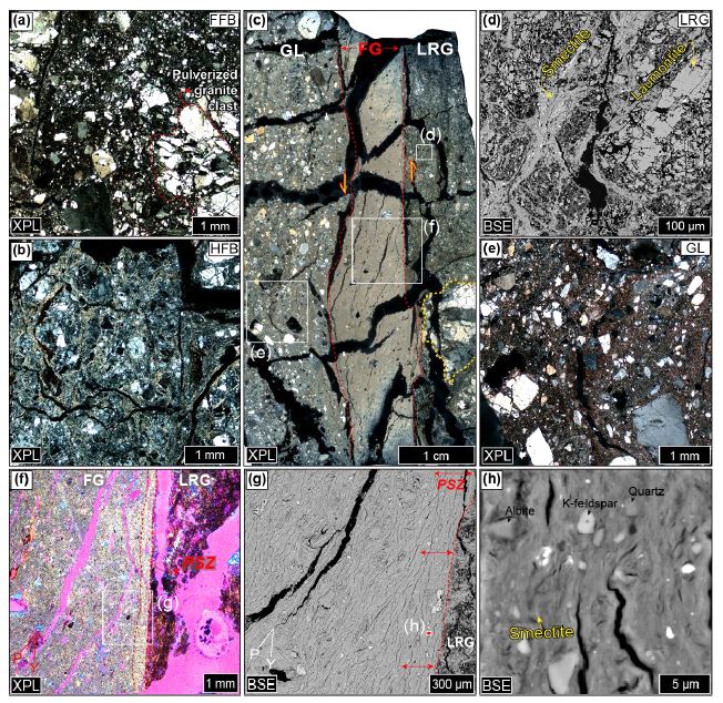
Microstructures of the fault rocks at Location 1. (a), (b) Photomicrographs of the footwall fault breccia (FFB) and hanging wall fault breccia (HFB), respectively. (c) Scanned thin-section image of the boxed area in Fig. 6a. The boundary between the fault gouge (FG) and laumontite-rich gouge (LRG) is more straight and planar than that between the FG and granitic lens (GL). (d), (e) Back-scattered electron (BSE) image and photomicrograph showing the LRG and GL, respectively. (f) Photomicrograph of the boundary between the FG and LRG. Here, a PSZ is characterized by strongly aligned clay minerals (gypsum plate inserted). (g) BSE image of the boxed area in (f). P-foliation is dominant in the FG, while the PSZ, indicated by the double-headed red arrows, shows a strong foliation parallel to the Y-shear direction. (h) Close-up view of the boxed area in (g). The PSZ is mainly composed of submicron-sized smectite grains.
2번 위치 암판의 가장 동편에 나타나는 FG2(그림 6c)는 주로 점토광물로 구성되어 있고 100-200 μm 크기의 석영과 장석 암편을 포함한다(그림 8a). FG2의 점토광물들은 국부적으로 정향배열을 보인다. FG와 QS★, LRG를 포함하는 박편에서, QS★와 FG의 경계는 굴곡져 있으며, FG 물질이 QS★쪽으로 주입된 형태가 관찰되는 반면, FG와 LRG의 경계는 직선적이고 날카롭게 나타난다(그림 8b). LRG는 광학현미경 하에서는 암편의 함량이 매우 적은 단층비지처럼 보이나(그림 8b), 전자현미경 관찰에서는 다량의 수백 μm 크기의 로몬타이트 암편과 스멕타이트로 이루어진 기질부가 확인된다(그림 8c). QS★는 규장질암, 이질암, 산화물, 운모 및 점토광물 등의 입자로 구성된 사력질 퇴적물이며, 이 영역에서는 점토광물의 정향배열 또는 파쇄와 같은 변형의 흔적은 명확히 인지되지 않는다(그림 8d). QS★ 쪽으로 주입되어 보이는 부분의 FG 물질은 주변에 비해 더 많은 양의 암편을 포함하고 있으며(그림 8b), 기질부의 점토광물들은 U자 형태로 정향배열하고 있다(그림 8e). FG는 주로 점토광물로 구성되며 최대 1 mm 크기의 암편을 포함한다(그림 8f). FG의 점토광물들은 전체적으로 정향배열을 보인다(그림 8f). FG 내부에 발달한 P-전단 방향의 엽리는 FG와 LRG의 경계로 갈수록 Y-전단 방향으로 자세가 변화한다(그림 8g). 여기서 Y-전단 방향의 엽리를 보이는 영역을 PSZ로 정의하였다(그림 8g). 이를 기준으로 보면 PSZ 폭은 대략 500 μm 정도이다(그림 8g). PSZ는 10 μm 이하 크기의 석영과 장석 암편, 그리고 1 μm 이하 크기의 스멕타이트 입자들로 구성된다(그림 8h).

Microstructures of the fault rocks at Location 2. (a) Photomicrograph of the fault gouge 2 (FG2). (b) Scanned thin-section image of the boxed area in Fig. 6c. Here, the fault gouge (FG) is injected into the QS★. (c) BSE image of the laumontite-rich gouge (LRG). (e) Photomicrograph of an area of the FG showing gouge injection (gypsum plate inserted). (f) Photomicrograph of the boundary between the FG and LRG (gypsum plate inserted). (g) BSE image of the boxed area in (f). A ~500 μm thick PSZ is developed, showing a strong foliation parallel to the Y-shear direction (double-headed red arrows). (h) Close-up view of the boxed area in (g). The PSZ mainly consists of submicron-sized smectite grains, which show a preferred orientation. QS★, Quaternary sediments about 1 cm away from the fault.
3-1번 위치에서 FG와 5 cm 이상 떨어진 영역의 QS는 규장질암, 이질암, 산화물, 운모 및 점토광물 등의 입자로 구성되며 점토광물의 정향배열 또는 파쇄와 같은 변형의 흔적은 관찰되지 않는다(그림 9a). FG, QS★ 및 DMD를 포함하는 박편에서, FG와 QS★ 그리고 FG와 DMD의 경계는 명확히 인지되며 완만한 물결 모양으로 나타난다(그림 9b). QS★는 QS에 비해 입자크기가 작고 기질부의 점토광물이 약한 정향배열을 보인다(그림 9a, 9c). QS★ 중 FG와 바로 접하고 있는 영역에서는 입자크기가 더 작고 점토광물의 정향배열이 강하다(그림 9c). DMD 는 암편의 함량이 매우 적고 대부분 점토질 물질로 구성되는데, 그 중 FG에 인접한 부분은 개방니콜에서 주변에 비해 더 어두운 색으로 나타난다(그림 9b). 이 영역의 열린 틈에는 주황색의 점토질 물질이 채워져 있는데(그림 9b, 적색 화살표), 이 주황색 물질은 직교니콜에서 주변보다 더 밝게 나타난다(그림 9d). DMD의 기질부 물질은 대부분 스멕타이트이고, 소량의 장석 암편을 포함하나 석영은 결핍되어 있다(그림 9e). 전자현미경 관찰 결과, 광학현미경에서 주황색으로 보인 물질은 주변보다 더 작은 크기의 스멕타이트로 확인되었다(그림 9e). FG와 바로 인접한 영역의 DMD는 매우 어두운 색으로 나타나고, 마치 파쇄된 듯한 형태로 FG 내부로 편입되어 있다(그림 9f). FG의 기질부 점토광물은 정향배열을 보이며, 약 1 mm 크기의 규장질 암편 및 DMD에서 떨어져 나온 것으로 보이는 어두운색 암편 등을 포함한다(그림 9f). 이 위치의 FG에서 P-전단 방향의 엽리와 PSZ는 관찰되지 않는다(그림 9f, 9g). 어두운색 암편은 주로 점토광물로 구성되며, 기질부와는 다른 정향배열을 보이는 단층비지암편(gouge clast; GC)의 형태로 산재해 있다(그림 9g, 9h). FG의 기질부는 약 100 μm 이내 크기의 석영, 장석, GC 및 스멕타이트로 구성된다(그림 9h). GC는 후방산란전자(BSE) 이미지에서 주변보다 더 밝게 나타나고, 대부분 스멕타이트로 구성되며, 그 내부에 포함된 암편은 모두 장석인 것으로 확인되었다(그림 9h).
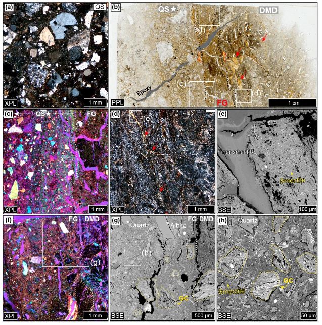
Microstructures of the fault rocks at Location 3-1. (a) Photomicrograph of the Quaternary sediment (QS) about 5 cm away from the fault. (b) Scanned thin-section image of the boxed area in Fig. 6e. (c) The boundary between the QS★ and fault gouge (FG). The QS★ consists of smaller grains than the QS and shows a preferred orientation of clay minerals (gypsum plate inserted). (d) Photomicrograph of the deformed mafic dike (DMD). (e) BSE image of the boxed area in (d). The DMD mainly consists of smectite. Some fractures in the DMD are filled with much smaller smectite grains than in the DMD. (f) Photomicrograph of the boundary between the FG and DMD. The FG shows a preferred orientation of clay minerals (gypsum plate inserted). (g) BSE image of the boxed area in (f). In the FG, no PSZ is observed, but many gouge clasts (GCs) are present. (g) Close-up view of the boxed area in (f) showing the matrix part of the FG. QS★: Quaternary sediments about 1 cm away from the fault. (h) Close-up view of the boxed area in (g) showing the GCs.
2번 위치에서는 FG가 단층에 대해 고각(>70°)으로 LRG쪽으로 주입된 구조가 관찰된다(그림 10a). 주입된 FG는 대부분 점토광물로 구성되며 소량의 석영, 장석 암편을 포함하고, 그 말단부에서는 점토광물의 U자형 정향배열을 보인다(그림 10b, 10c).
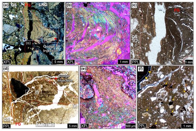
Microstructures of the gouge injections at Locations 2 and 3-2. (a) Scanned thin-section image of the boxed area in Fig. 6g. The fault gouge (FG) is injected into the laumontite-rich gouge (LRG). (b) Photomicrograph of the tip of the gouge injection (boxed area in (a)), where a U-shaped alignment of clay minerals is observed (gypsum plate inserted). (c) The gouge injection mainly consists of clay minerals and clasts of quartz and feldspar (boxed area in (a)). (d) Scanned thin-section image of the boxed area in Fig. 6h. The FG is injected into the deformed mafic dike (DMD) and mafic dike (MD). (e) Photomicrograph of the tip of the gouge injection (boxed area in (d)) showing a U-shaped alignment of clay minerals (gypsum plate inserted). (f) The gouge injection includes quartz, mudstone, and granitic rock clasts that exist in neither the DMD nor MD. QS, Quaternary sediments.
3-2번 위치에서는 FG가 단층에 대해 고각(>70°)의 자세로 변형된 DMD 또는 MD쪽으로 주입되어 있다(그림 10d). 주입된 FG 내부에는 어두운 색을 띠는 약 0.5 cm 크기의 산화물 암편이 포함되어 있다(그림 10d). 2번 위치에서와 마찬가지로, 주입된 단층비지의 말단부에서는 점토광물이 U자 형태의 정향배열을 보인다(그림 10e). 이 주입된 FG에 포함된 석영, 이질암편 및 산화물 암편은 MD에는 존재하지 않고 QS에 다량 포함된 것들이다(그림 10f).
6. 토 의
6.1 지진성미끌림의 지질학적 기록
자연 단층 연구에 적용 가능한 신뢰할만한 지진성미끌림 지시자가 무엇인지에 대한 논의가 시작된 이후로(e.g., Cowan, 1999), 지금까지 자연 단층 관찰 및 실내 전단시험을 통해 다양한 지질학적 특징들이 지진성미끌림 지시자 측면에서 토의되어 왔으며(e.g., Rowe and Griffith, 2015), 이들 중 일부는 제4기 단층 연구에 적용되었다(Cashman et al., 2007; Janssen et al., 2014; Han et al., 2020; Kim, C.-M. et al., 2020). 이 절에서는 연구대상 주단층의 단층핵 및 손상대에서 관찰된 분쇄화강암(PG), 단층비지 주입구조(세맥), 좁은 폭의 주미끌림대를 대상으로 그것들의 지진성미끌림 지시 여부에 대해 간략히 논의한다.
연구지역 주단층 주변으로 분포하는 PG는 상반에서보다 하반에서 더 폭넓게 나타나고(그림 2b), 맨손으로도 쉽게 부스러지는 특징을 갖는다(그림 2d). 단열화강암(FRG)과 PG의 광물조성이 거의 유사함에도(그림 4e) PG만 심하게 파쇄된 것으로 보아 PG의 발달은 화학적 풍화보다는 물리적인 요인에 의한 것으로 해석된다. 하나의 입자가 확장 미소단열에 의해 다수의 미세입자로 분리되어 있는 모습(그림 5b)과 화강암의 일차적인 암석조직은 대체로 유지하고 있는 점(그림 4b, 5b) 등은 앞서 서론에서 언급한 분쇄암의 전형적인 특징과 일치한다. 따라서, 천군동2지점에서 확인되는 PG는 이 단층을 따라 발생한 지진성미끌림과 직접적으로 연관된 것으로 해석할 수 있다.
단층 주변의 기존 단열이나 새로이 만들어지는 확장단열은 다양한 지질 물질이 주입되어 채워질 수 있는데 이를 단층물질의 주입구조 또는 주입 세맥(injection vein)이라고 한다(Rowe et al., 2012; Rowe and Griffith, 2015). 자연 단층에서 주입세맥을 이루는 물질은 슈도타킬라이트(Han, 2017; Kang et al., 2017, 2019; Han et al., 2019; Kim, C.-M. et al., 2019), 점토광물로 탈유리화된 슈도타킬라이트(Gu et al., 2021), 초파쇄암(ultracataclasite; Lin, 1996; Lin, 2011) 및 점토질 단층비지(clay-rich gouge; Han et al., 2020; Gu et al., 2021; Kim, C.-M. et al., 2022) 등이 있다. 이 중 단층비지(FG) 주입세맥은 물을 포함하며 낮은 투수율을 갖는 단층암 내에서 빠른 미끌림이 발생할 때 마찰가열에 의한 온도상승, 일시적인 비배수조건(undrained condition)에서의 유체압 상승으로 인해 높은 압력을 갖게 된 FG가 주변암으로 주입하면서 만들어진 구조이다(Ferri et al., 2010, 2011; Lin, 2011; Ujiie et al., 2013; Rowe and Griffith, 2015; Han et al., 2020). 이러한 이유로 주입세맥은 빠른 미끌림, 즉 지진성미끌림의 지시자가 될 수 있다. 주입되는 과정에서 입자의 배열이 발생하므로 주입세맥 내에서는 점토광물의 배열에 의한 U자 형태의 구조가 나타날 수 있다(e.g., Woo et al., 2016; Cheon et al., 2020b; Han et al., 2020; Gu et al., 2021). 연구대상 주단층의 2번 위치와 3-2번 위치에서는 FG가 단층면에 고각의 자세로 상반(PG 및 MD)쪽으로 주입되어 있고(그림 3c, 3e, 6g, 6h), 2번 위치에서는 FG가 하반(QS)쪽으로 주입된 구조 또한 나타난다(그림 8b, 8e). 단층비지세맥 내에서는 주입 당시 형성된 것으로 보이는 점토광물의 U자형 정향배열이 관찰된다(그림 10b, 10e). 따라서, 이와 같은 FG 주입세맥은 그 단층을 따라 과거 지진성미끌림이 발생하였음을 지시한다.
자연 단층의 핵에서 PSZ는 수 μm에서 수 cm 폭으로 발달한다(Sibson, 2003; Chester et al., 2003; De Paola et al., 2008; Han et al., 2020; Gu et al., 2021; Kim, C.-M. et al., 2022). 실험단층에서 이러한 PSZ는 >0.1 m/s 이상의 지진성 미끌림속도를 경험한 비지에서 다수 관찰되어왔다(e.g., Brantut et al., 2008; Yao et al., 2013; Aretusini et al., 2019; Han et al., 2020), 그러나, 저속 미끌림실험에서는 불안정한 고착-미끌림(stick-slip)을 보인 경우 뿐 아니라 안정하게 미끌린 단층비지에서도 PSZ가 관찰되므로(Ikari, 2015; Aretusini et al., 2019) 이 구조가 과연 자연 단층에서의 지진성미끌림을 지시하는지는 아직까지 불명확하다. 연구대상 주단층의 경우 1번 및 2번 위치의 FG 내부에는 Y-전단 방향으로의 강한 엽리가 특징적인 PSZ가 약 300-500 μm 폭으로 발달하며(그림 7g, 7h, 8g, 8h), FG와 PSZ는 주로 스멕타이트로 구성된다(그림 6b, 6d, 7h, 8h). 스멕타이트가 풍부한 FG의 경우, 기존 실험연구의 저속 및 고속미끌림 모두에서 PSZ가 발달한다는 관찰결과가 보고된 바 있다(Aretusini et al., 2019). 따라서, 그 구조가 발달한다는 점 하나만으로는 지진성미끌림 발생여부를 단정하기 힘들기 때문에 그것을 지진성미끌림의 잠재적 발생가능영역 정도로 생각하는 것이 일반적으로는 합리적이다. 다만, 본 연구대상 단층의 경우에는 추가적인 증거, 즉 그 내부에 PSZ가 발달하는 FG가 주변으로 주입된 구조를 보이고 있으므로(그림 8) 그 PSZ의 발달과 지진성미끌림은 직접적으로 관련되었을 가능성이 높다.
6.2 제4기 지진성미끌림의 기록
제4기 단층이라도 느리고 안정한 미끌림이 발생할 수 있으므로 지진재해와 관련하여 단층을 연구하는 입장에서는 그 단층을 따라 제4기에 지진성미끌림이 발생했는지의 여부가 특히 중요하다. 따라서, 6.1절에서 지진성미끌림 지시자로 언급된 것들이라도 그것이 제4기 이전의 미끌림과 제4기 미끌림 중 어느 것과 관련된 것인지를 판별할 필요가 있다. 이 절에서는 앞서 언급한 구조들 중 제4기에 형성된 구조는 어떤 것인지에 대해 간략히 논의한다.
연구대상 주단층에서는 2번 및 3-2번 위치에서 FG 주입구조가 관찰되는데, 그 중 2번 위치에서는 상반의 PG쪽으로 주입된 것(그림 3c)뿐 아니라 하반쪽으로 주입된 것(그림 8b)도 존재한다. 전자의 경우 FG 내 암편이 석영과 장석으로 구성되어(그림 10c) 주변 물질과 차이를 보이지 않기 때문에 제4기 지진성미끌림과 관련한 것인지가 불확실하다. 반면, 후자의 경우(그림 8b)는 FG가 QS쪽으로 주입되었으므로(그림 8b, 8e), 이 구조는 제4기에 만들어진 것으로 해석할 수 있다. 3-2번 위치에서 관찰되는 FG 주입구조의 경우, 그 주입방향이 상반 모암인 MD쪽이기는 하나(그림 6h), 주입된 FG 내부에는 MD 암편뿐 아니라 MD에는 없고 QS에 존재하는 물질(규장질암, 이질암, 산화물 암편 등)이 포함되어 있다(그림 10f). 아울러, MD 또는 DMD에는 결핍된 석영이(그림 4e, 6h) 주입된 FG에 다량으로 포함된 점(그림 10f) 등은 이 위치의 FG가 QS와 MD가 섞여서 형성된 것이며 그 물질이 상반으로 주입된 시점이 QS가 지표에 퇴적된 이후, 즉 제4기라는 것을 의미한다.
PG의 경우 미소단열이 모두 열린 단열 상태를 보이는데, 시간에 따라 열린 단열은 유체의 도움 하에 광물로 채워지거나 치유되어 점차 봉합된다는 사실에 비추어 볼 때, 이는 분쇄화작용이 아주 오래되지 않은 시점에 발생하였거나 오래 전에 시작된 분쇄화작용이 이후에도 반복적으로 발생했을 가능성을 시사한다. 가령, 일본의 한 제4기 단층연구에 따르면 제4기에 활동한 단층의 경우에는 열린 단열이 관찰되고 제4기 이전에 활동하다가 제4기에는 활동하지 않은 단층은 모두 봉합된 단열(healed fracture)을 보인다는 점을 보고한 바 있다(Mizoguchi and Ueta, 2013). 또한 Arima-Takatsuki 구조선과 같이 제4기에 활동중인 단층에서의 분쇄암은 열린 단열을 보여준다(Mitchell et al., 2011). 현재까지 본 연구단층에서 확인되는 분쇄화작용의 시기를 밝힐 수 있는 방법은 없으나, 분쇄암 내 단열의 봉합여부가 분쇄화작용의 대략적인 시기규정에 효과적으로 사용될 수 있는지를 검토하는 추가적인 연구가 필요해 보인다.
7. 결 론
본 연구는 천군동지역 제4기 단층을 대상으로 손상대 및 단층핵의 물질과 미구조 분석을 통해 제4기 지진성미끌림 기록을 찾기 위해 수행되었다. 지진성미끌림과 직접적으로 관련된 것으로 보이는 특징은 손상대에서 관찰되는 분쇄화강암과 단층핵을 따라 여러 위치에서 나타나는 단층비지 주입구조이다. 이 중 분쇄화강암의 형성이나 상부 모암으로의 단층비지 주입의 경우 그것들의 제4기 발생여부가 확실치 않다. 반면, 제4기 퇴적물쪽으로 주입된 비지와 제4기 퇴적물을 포함하면서 고철질암맥으로 주입된 비지의 경우는 연구대상 단층을 따라 제4기 지진성미끌림이 발생하였음을 분명히 지시한다. 이번 연구는 지진성미끌림 지시자의 상세 구조관찰이 제4기 이전부터 활동해온 단층의 제4기 지진성미끌림 여부를 판별하는데 효과적으로 활용될 수 있음을 보여준다. 한편, 단층핵 내 주미끌림대 발달이 지진성미끌림을 지시하는지, 분쇄화강암의 상태(가령, 그 내부의 단열들의 열림 또는 봉합 여부)가 제4기 지진성미끌림 발생 여부에 대한 정보를 줄 수 있는지와 같은 중요한 문제들에 대해 답하기 위한 추가 연구가 필요하다.
Acknowledgments
이 연구는 2022년도 정부(과학기술정보통신부)의 재원으로 한국연구재단의 지원 (No. 2019R1A2C1008082)과 행정안전부 지진위험분석 및 관리기술 개발사업의 지원(2022-MOIS62-001)을 받아 수행되었습니다. 세심한 심사를 통해 본 논문의 질적향상에 도움을 주신 두 분의 익명 심사위원과 편집위원께 감사드립니다.
References
-
Aben, F.M., Doan, M.L., Mitchell, T.M., Toussaint, R., Reuschlé, T., Fondriest, M., Gratier, J.P. and Renard, F., 2016, Dynamic fracturing by successive coseismic loadings leads to pulverization in active fault zones. Journal of Geophysical Research: Solid Earth, 121, 2338-2360.
[https://doi.org/10.1002/2015JB012542]

-
Aretusini, S., Plümper, O., Spagnuolo, E. and Di Toro, G., 2019, Subseismic to seismic slip in smectite clay nanofoliation. Journal of Geophysical Research: Solid Earth, 124, 6589-6601.
[https://doi.org/10.1029/2019JB017364]

-
Boutareaud, S., Calugaru, D.-G., Han, R., Fabbri, O., Mizoguchi, K., Tsutsumi, A. and Shimamoto, T., 2008, Clay-clast aggregates: A new textural evidence for seismic fault sliding?. Geophysical Research Letters, 35.
[https://doi.org/10.1029/2007GL032554]

-
Brantut, N., Schubnel, A., Rouzaud, J.N., Brunet, F. and Shimamoto, T., 2008, High‐velocity frictional properties of a clay‐bearing fault gouge and implications for earthquake mechanics. Journal of Geophysical Research: Solid Earth, 113.
[https://doi.org/10.1029/2007JB005551]

- Brune, J.N., 2001, Fault-normal dynamic unloading and loading: An explanation for "non-gouge" rock powder and lack of fault-parallel shear bands along the San Andreas Fault. American Geophysical Union, Fall Meeting, Abstract S22B-0655.
-
Cashman, S.M., Baldwin, J.N., Cashman, K.V., Swanson, K. and Crawford, R., 2007, Microstructures developed by coseismic and aseismic faulting in near-surface sediments, San Andreas fault, California. Geology, 35, 611-614.
[https://doi.org/10.1130/G23545A.1]

-
Cheon, Y., Choi, J.-H., Choi, Y., Bae, H., Han, K.-H., Son, M., Choi, S.-J. and Ryoo, C.-R., 2020a, Understanding the distribution and internal structure of the main core of the Yangsan Fault Zone: Current trends and future work. Journal of the Geological Society of Korea, 56, 619-640 (in Korean with English abstract).
[https://doi.org/10.14770/jgsk.2020.56.5.619]

-
Cheon, Y., Choi, J.-H., Kim, N., Lee, H., Choi, I., Bae, H., Rockwell, T., Lee, S., Ryoo, C.-R., Choi, H. and Lee, T.H., 2020b, Late Quaternary transpressional earthquakes on a long-lived intraplate fault: A case study of the Southern Yangsan Fault, SE Korea. Quaternary International, 553, 132-143.
[https://doi.org/10.1016/j.quaint.2020.07.025]

- Chester, J.S., Kronenberg, A.K., Chester, F.M. and Guillemette, R.N., 2003, Characterization of natural slip surfaces relevant to earthquake mechanics. American Geophysical Union, Fall Meeting, Abstract S42C-0185.
-
Cowan, D.S., 1999, Do faults preserve a record of seismic slip? A field geologist's opinion. Journal of Structural Geology, 8, 995-1001.
[https://doi.org/10.1016/S0191-8141(99)00046-2]

-
De Paola, N., Collettini, C., Faulkner, D.R. and Trippetta, F., 2008, Fault zone architecture and deformation processes within evaporitic rocks in the upper crust. Tectonics, 27.
[https://doi.org/10.1029/2007TC002230]

-
Doan, M.L. and Gary, G., 2009, Rock pulverization at high strain rate near the San Andreas fault. Nature Geoscience, 2, 709-712.
[https://doi.org/10.1038/ngeo640]

-
Dor, O., Ben-Zion, Y., Rockwell, T.K. and Brune, J., 2006, Pulverized rocks in the Mojave section of the San Andreas Fault Zone. Earth and Planetary Science Letters, 245, 642-654.
[https://doi.org/10.1016/j.epsl.2006.03.034]

-
Ferri, F., Di Toro, G., Hirose, T., Han, R., Noda, H., Shimamoto, T., Quaresimin, M. and De Rossi, N., 2011, Low- to high-velocity frictional properties of the clay-rich gouges from the slipping zone of the 1963 Vaiont slide, northern Italy. Journal of Geophysical Research, 116.
[https://doi.org/10.1029/2011JB008338]

-
Ferri, F., Di Toro, G., Hirose, T. and Shimamoto, T., 2010, Evidence of thermal pressurization in high‐velocity friction experiments on smectite‐rich gouges. Terra Nova, 22, 347-353.
[https://doi.org/10.1111/j.1365-3121.2010.00955.x]

-
Fondriest, M., Aretusini, S., Di Toro, G. and Smith, S.A., 2015, Fracturing and rock pulverization along an exhumed seismogenic fault zone in dolostones: The Foiana fault zone (Southern Alps, Italy). Tectonophysics, 654, 56-74.
[https://doi.org/10.1016/j.tecto.2015.04.015]

-
Gu, D., Han, R. and Woo, S., 2021, Geological records of coseismic shear localization along the Yangsan fault, Korea. Journal of Geophysical Research: Solid Earth, 126, e2020JB021393.
[https://doi.org/10.1029/2020JB021393]

-
Han, R., 2017, Pseudotachylytes and seismic fault slip. Journal of the Geological Society of Korea, 53, 159-171 (in Korean with English abstract).
[https://doi.org/10.14770/jgsk.2017.53.1.159]

-
Han, R., Hirose, T., Jeong, G.Y., Ando, J. and Mukoyoshi, H., 2014, Frictional melting of clayey gouge during seismic fault slip: experimental observation and implications. Geophysical Research Letters, 41, 5457-5466.
[https://doi.org/10.1002/2014GL061246]

-
Han, R., Kim, C.-M., Woo, S., Jeong, G.Y. and Hirose, T., 2020, Structural records and mechanical characteristics of seismic slip along an active fault crosscutting unconsolidated Quaternary sediments: Suryum fault, SE Korea. Geosciences Journal, 24, 379-389.
[https://doi.org/10.1007/s12303-019-0037-4]

-
Han, R., Kim, J.-S., Kim, C.-M., Hirose, T., Jeong, J.O. and Jeong, G.Y., 2019, Dynamic weakening of ring faults and catastrophic caldera collapses. Geology, 47, 107-110.
[https://doi.org/10.1130/G45687.1]

-
Harris, R.A., 2017, Large earthquakes and creeping faults. Reviews of Geophysics, 55, 169-198.
[https://doi.org/10.1002/2016RG000539]

-
Heynekamp, M.R., Goodwin, L.B., Mozley, P.S. and Haneberg, W.C., 1999, Controls on fault‐zone architecture in poorly lithified sediments, Rio Grande Rift, New Mexico: Implications for fault‐zone permeability and fluid flow. In: Haneberg, W., Mozley, P., Moore, J. and Goodwin, L. (eds.), Faults and Subsurface Fluid Flow in the Shallow Crust, Geophysical Monograph Series, 113, 27-49.
[https://doi.org/10.1029/GM113p0027]

-
Ikari, M.J., 2015, Principal slip zones: Precursors but not recorders of earthquake slip. Geology, 43, 955-958.
[https://doi.org/10.1130/G37028.1]

-
Janssen, C., Wirth, R., Wenk, H.R., Morales, L., Naumann, R., Kienast, M. and Dresen, G., 2014, Faulting processes in active faults-evidences from TCDP and SAFOD drill core samples. Journal of Structural Geology, 65, 100-116.
[https://doi.org/10.1016/j.jsg.2014.04.004]

- Jeong, S.H., Naik, S.P. and Kim, Y.S., 2018, A study on Quaternary faulting in the northwestern part of the Ulsan fault at Cheongundong, Gyeongju. 2018 Fall Joint Conference of the Geological Sciences of Korea (Abstracts), Gyeongju, October 24-27, p. 255 (in Korean).
- Kang, D.H., 2019, A study on the anisotropy of magnetic susceptibility (AMS) of the Quaternary faults rock, SE Korea. MS Thesis, Pusan National University, Pusan, 96 p (in Korean with English abstract).
-
Kang, H.-C., Han, R., Kim, C.-M., Cheon, Y., Cho, H., Yi, K., Son, M. and Kim, J.-S., 2017, The Bonggil pseudotachylyte, SE Korea: Its occurrence and characteristics. Journal of the Geological Society of Korea, 53, 173-191 (in Korean with English abstract).
[https://doi.org/10.14770/jgsk.2017.53.1.173]

- Kang, H.-C., Kim, C.-M., Han, R., Ryoo, C.-R., Son, M. and Lee, S.-W., 2019, Pseudotachylyte developed in granitic gneiss around the Bulil waterfall in the Jirisan, SE Korea: Its occurrence and characteristics. Journal of the Petrological Society of Korea, 28, 157-169 (in Korean with English abstract).
-
Kim, C.-M., Cheon, Y., Han, R., Jeong, G.Y. and Jeong, J.O., 2022, Fault reactivation with rapid slip along subsidiary faults in the Yangsan Fault zone, SE Korea. Geosciences Journal, 26, 167-181.
[https://doi.org/10.1007/s12303-021-0027-1]

-
Kim, C.-M., Ha, S. and Son, M., 2020, Evidence of coseismic slip recorded by Quaternary fault materials and microstructures, Naengsuri, Pohang. Journal of the Geological Society of Korea, 56, 175-192 (in Korean with English abstract).
[https://doi.org/10.14770/jgsk.2020.56.2.175]

-
Kim, C.-M., Han, R., Kim, J.-S., Sohn, Y.K., Jeong, J.O., Jeong, G.Y., Yi, K. and Kim, J.C., 2019, Fault zone processes during caldera collapse: Jangsan Caldera, Korea. Journal of Structural Geology, 124, 197-210.
[https://doi.org/10.1016/j.jsg.2019.05.002]

-
Kim, C.-M., Jeong, J.O., Gu, D. and Han, R., 2017, Identification of materials in principal slip zones of faults by X-ray diffraction analysis using a small amount of sample. Journal of the Geological Society of Korea. 53, 873-883 (in Korean with English abstract).
[https://doi.org/10.14770/jgsk.2017.53.6.873]

-
Kim, M.-C., Jung, S., Yoon, S., Jeong, R.-Y., Song, C.-W. and Son, M., 2016, Neotectonic crustal deformation and current stress field in the Korean peninsula and their tectonic implications: A review. Journal of the Petrological Society of Korea, 25, 169-193 (in Korean with English abstract).
[https://doi.org/10.7854/JPSK.2016.25.3.169]

-
Kim, M.-J. and Lee, H.-K., 2020, ESR dating of fault gouge - review. Journal of the Geological Society of Korea, 56, 211-234 (in Korean with English abstract).
[https://doi.org/10.14770/jgsk.2020.56.2.211]

- Kim, Y.-S., Jin, K., Choi, W.-H. and Kee, W.-S., 2011, Understanding of active faults: A review for recent researches. Journal of the Geological Society of Korea, 47, 723-752 (in Korean with English abstract).
-
Kim, Y.-S., Son, M., Choi, J.-H., Choi, J.-H., Seong, Y.B. and Lee, J., 2020, Processes and challenges for the production of Korean active faults map. Journal of the Geological Society of Korea, 56, 113-134 (in Korean with English abstract).
[https://doi.org/10.14770/jgsk.2020.56.2.113]

-
Lee, J., Rezaei, S., Hong, Y., Choi, J.-H., Choi, J.-H., Choi, W.-H., Rhee, K.-W. and Kim, Y.-S., 2015, Quaternary fault analysis through a trench investigation on the northern extension of the Yangsan fault at Dangu-ri, Gyungjusi, Gyeongsanbuk-do. Journal of the Geological Society of Korea, 51, 471-485 (in Korean with English abstract).
[https://doi.org/10.14770/jgsk.2015.51.5.471]

-
Lin, A., 1996, Injection veins of crushing-originated pseudotachylyte and fault gouge formed during seismic faulting. Engineering Geology, 43, 213-224.
[https://doi.org/10.1016/0013-7952(96)00062-2]

-
Lin, A., 2011, Seismic slip recorded by fluidized ultracataclastic veins formed in a coseismic shear zone during the 2008 Mw 7.9 Wenchuan earthquake. Geology, 39, 547-550.
[https://doi.org/10.1130/G32065.1]

- McCalpin, J.P., 2009, Paleoseismology: 2nd ed. Academic Press, San Diego, 613 p.
-
Mitchell, T.M., Ben-Zion, Y. and Shimamoto, T., 2011, Pulverized fault rocks and damage asymmetry along the Arima-Takatsuki Tectonic Line, Japan. Earth and Planetary Science Letters, 308, 284-297.
[https://doi.org/10.1016/j.epsl.2011.04.023]

-
Mizoguchi, K. and Ueta, K., 2013, Microfractures within the fault damage zone record the history of fault activity. Geophysical Research Letters, 40, 2023-2027.
[https://doi.org/10.1002/grl.50469]

-
Otsuki, K., Minagawa, J., Aono, M. and Ohtake, M, 1997, On the curved striations of Nojima seismic fault engraved at the 1995 Hyogoken-Nambu earthquake, Japan. Jishin, 49, 451-460 (in Japanese with English abstract).
[https://doi.org/10.4294/zisin1948.49.4_451]

-
Park, H.-J., Han, R. and Gu, D., 2020, Structures and deformation characteristics of the Quaternary slip fault, Hwalseongri, Gyeongju, Korea. Journal of the Geological Society of Korea, 56, 703-726 (in Korean with English abstract).
[https://doi.org/10.14770/jgsk.2020.56.6.703]

-
Ree, J.-H., Lee, Y.-J., Rhodes, E.J., Park, Y., Kwon, S.-T., Chwae, U., Jeon, J.-S. and Lee, B.-J., 2003, Quaternary reactivation of Tertiary faults in the southeastern Korean peninsula: Age constraint by optically stimulated luminescence dating. The Island Arc, 12, 1-12.
[https://doi.org/10.1046/j.1440-1738.2003.00372.x]

-
Rempe, M., Mitchell, T., Renner, J., Nippress, S., Ben‐Zion, Y. and Rockwell, T., 2013, Damage and seismic velocity structure of pulverized rocks near the San Andreas Fault. Journal of Geophysical Research: Solid Earth, 118, 2813-2831.
[https://doi.org/10.1002/jgrb.50184]

-
Rowe, C.D. and Griffith, W.A., 2015, Do faults preserve a record of seismic slip: A second opinion. Journal of Structural Geology, 78, 1-26.
[https://doi.org/10.1016/j.jsg.2015.06.006]

-
Rowe, C.D., Kirkpatrick, J.D. and Brodsky, E.E., 2012, Fault rock injections record paleo-earthquakes. Earth and Planetary Science Letters, 335, 154-166.
[https://doi.org/10.1016/j.epsl.2012.04.015]

-
Sibson, R.H., 2003, Thickness of the seismic slip zone. Bulletin of the Seismological Society of America, 93, 1169-1178.
[https://doi.org/10.1785/0120020061]

-
Sullivan, W.A. and Peterman, E.M., 2017, Pulverized granite at the brittle-ductile transition: An example from the Kellyland fault zone, eastern Maine, USA. Journal of Structural Geology, 101, 109-123.
[https://doi.org/10.1016/j.jsg.2017.07.002]

- Tateiwa, I., 1924, Geological Atlas of Chosen, No. 2, Ennichi, Kuryuho and Choyo sheet (1:50,000). Geological Survey of Chosen (in Japanese).
-
Ujiie, K., Tanaka, H., Saito, T., Tsutsumi, A., Mori, J.J., Kameda, J., Brodsky, E., Chester, F., Eguchi, N. and Toczko, S., 2013, Low coseismic shear stress on the Tohoku-Oki megathrust determined from laboratory experiments. Science, 342, 1211-1214.
[https://doi.org/10.1126/science.1243485]

-
Woo, S., Han, R., Kim, C.-M., Jeong, G.Y., Jeong, J.O. and Lee, H., 2016, Relation between temporal change of fault rock materials and mechanical properties. Journal of the Geological Society of Korea, 52, 847-861 (in Korean with English abstract).
[https://doi.org/10.14770/jgsk.2016.52.6.847]

-
Yao, L., Ma, S., Shimamoto, T. and Togo, T., 2013, Structures and high-velocity frictional properties of the Pingxi fault zone in the Longmenshan fault system, Sichuan, China, activated during the 2008 Wenchuan earthquake. Tectonophysics, 599, 135-156.
[https://doi.org/10.1016/j.tecto.2013.04.011]

- Yeats, R.S., Sieh, K. and Allen, C.R., 1997, The Geology of Earthquakes. Oxford University Press, New York, 568 p.
-
Yuan, F., Prakash, V. and Tullis, T., 2011, Origin of pulverized rocks during earthquake fault rupture. Journal of Geophysical Research: Solid Earth, 116.
[https://doi.org/10.1029/2010JB007721]

