가상 반사파 영상 작성을 위한 비반사파 신호 및 공중점 범위에 관한 고찰
초록
지표면 1차 다중반사파를 이용한 가상 반사파 영상법이 널리 사용되지 못하는 원인을 밝히고 해결 방안을 제시코자, 지진파 자료를 합성하고 가상반사파 자료를 작성한 후 그 특성을 분석하였다. 합성지진파 자료는 수직 단층대가 존재하는 수평 2층 구조 모델을 대상으로 5개 파원에서 독립적으로 발생시킨 파형이 99개 수신기 위치에 도달한 것을 모의하여 유한차분법으로 구하였다. 이 자료는 반사파 신호의 최대진폭이 직접파로 전파된 레일리파의 평균 2% 이내로 매우 미약함을 보였다. 이는 트레이스 상호상관 이전에 비반사파 신호들이 최대한 억제되어야 좋은 가상반사파 영상을 얻을 수 있음을 지시한다. 가상반사파의 불변위상 특성을 고려할 때, 수평중합할 공중점 범위는 파원으로부터 상호상관 트레이스 쌍의 가까운 수신기까지 거리에 수신기 간격의 절반을 더한 거리를 넘지 않아야 한다. 또한 가상반사영상의 신호대-잡음비를 높이기 위해서는 반사파 진폭이 큰 공중점 범위도 고려 대상에 포함시켜야 한다.
Abstract
To find major obstacles to the broad implementation of and to suggest effective processing methods for virtual reflection images using the first surface multiples, seismic data were synthesized and the characteristics of the virtual reflection data were analyzed. For the synthetic data for the two-layer horizontal model with a vertical boundary, seismic energy was assumed to be generated at five independent sources and their waveforms were computed at 99 receiver locations. Maximum amplitudes of reflection signals are less than 2% of those of the direct Rayleigh waves on an average. This indicates that the non-reflection seismic events should be suppressed before correlating traces for virtual seismic data with good signal-to-noise ratios. The stationary phase of virtual reflections should be considered in determination of the optimum common-midpoint (CMP) ranges for horizontal stacking. Additionally, the CMP ranges with large reflection amplitudes should be also considered for good signal-to-noise ratios of virtual stack images.
Keywords:
virtual reflection image, synthetic data, stationary phase, CMP range키워드:
가상 반사파, 합성지진파, 불변위상, 공중점 범위1. 서 론
뉴우톤의 환을 비롯한 빛의 간섭현상이 과학자들의 관심을 끈 지는 이미 한 세기 이상이 흘렀지만, 간섭법(interferometry)이 지구 내부구조를 밝히는데 사용되기 시작한 것은 그리 오래되지 않았다. 지표에서의 그린함수(Green’s function)를 지하에서 발생된 지진파 신호의 자기상관함수(autocorrelation)로 부터 구할 수 있음을 보인 Claerbout (1968)의 연구를 지진파 간섭법(seismic interferometry)의 효시로 볼 수 있다. 이 후의 발달과정, 배경이론, 한계 및 적용 예 등은 Schuster (2009)가 상세히 기술한 바 있다.
지진파 간섭법은 모든 수신기가 가상파원(virtual source)이 되므로 자료의 양이 대폭 늘어나고, 이에 따라 목표물의 범위도 크게 증가하게 된다. 또한 재기준화(redatuming)를 통한 목표물의 근접 영상을 구할 수 있어서 분해능을 높일 수 있는 장점이 있다(Schuster, 2009). 그러나 일반적으로 신호대-잡음비가 낮은 문제를 해결해야 하며, 기록시간이 길어지는 단점도 있다. 지진배경잡음(seismic ambient noise)은 항시적이며 주로 표면파로 구성되어 있어서 지표 수신기에 강하게 기록되기 때문에, 간섭법을 적용하기에 적합한 지진파의 일종이다. 따라서 배경잡음을 이용하여 토모그래피 방식으로 지각구조를 밝히는 연구가 성공적으로 수행된 사례는 여러 차례 보고된 바 있다(Campillo and Paul, 2003; Shapiro et al., 2005; Kang and Shin, 2006; Cho et al., 2007). 그밖에도 수동적 지진파 간섭법 중, 원거리 지진의 코다파(Snieder et al., 2004; Abe et al., 2007)를 이용한 연구도 좋은 결과를 보여주고 있다.
한편 능동적 방법은 Calvert et al. (2004)이 가상파원(virtual source)이란 명칭으로 수직탄성파(vertical seismic profiling) 자료를 단일 시추공탐사(single well profiling) 자료로 재기준화 할 수 있음을 보인 후에, 반사된 실체파를 이용한 연구가 석유가스탐사 분야를 중심으로 수행되고 있다(Bolshakov et al., 2011; Grechka and Zhao, 2012). 그러나 아직도 실용화 단계에 이르렀다고는 볼 수 없으며, 반사된 P파 신호를 추출하는데 초점을 맞추는 등 초보적인 단계에 머무르고 있는 실정이다(e.g., Ruigrok et al., 2011). 국내에서는 최근 합성지진파 자료를 이용하여 반사파 간섭영상의 신호대-잡음비를 높이기 위한 연구가 일부 진행 중이다(Kim et al., 2018; Song et al., 2018).
우리는 가상반사법(virtual reflection method)이 많은 장점을 갖고 있음에도 널리 사용되고 있지 못한 원인을 찾아보고, 해결 방안을 제시코자 한다. 이를 위하여 이 논문에서는 지진파 간섭법에 관한 기초이론을 간단히 소개하고, 수치탄성모델(numerical elastic model)을 대상으로 합성지진파 자료를 제작한다. 이를 이용하여 가상지진파 자료의 특성을 밝히며, 자료처리과정에서 유의할 점을 제시코자 한다.
2. 이론적 배경
지진파 간섭법에 관한 이론은 Schuster (2009)나 Wapenaar et al. (2010) 등이 자세히 설명한 바 있으므로, 여기서는 간략히 개념만을 기술한다. 동일한 파원 S에서 발생된 지진파가 XR1에 위치한 수신기 R1을 거쳐서 XR2에 위치한 수신기 R2에 도달한 경우, 두 수신기에 기록된 자료를 상호상관하면, 파원에서 R1까지 경로와는 무관하게 R1과 R2 사이의 그린(Green’s)함수를 구할 수 있다는 것이다(그림 1). 이를 식으로 표시하면,
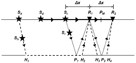
Schematic diagram of raypaths for direct wave (thick solid), critical refraction (dashed), and reflection (dotted) interferometry with two receivers, R1 and R2 (triangles), in a homogeneous two-layer layer model. Stationary source locations (stars) can be in any position along the profile away from the two receivers for the direct waves (Sd), farther than the critical distance from the nearer receiver for the critically refracted waves (Sh), and only at the distance equal to the separation of paired receivers (Δx) from the nearer receiver (Sr) and its multiples for reflected waves. Buried stationary source locations (Sh and Sr) and midpoint (PM) are also indicated (modified from Song et al., 20018).
| (1) |
으로, 여기서 G는 그린함수, *는 곱쌓기(convolution), ⊗는 상호상관(cross-correlation), 괄호 안의 인수는 차례로 수신기 위치, 파원 위치, 주시를 각각 나타내며, ΦS(t)는 파형요소의 자기상관함수(auto-correlation function), u(t)는 파형요소와 그린함수의 곱쌓기를 뜻한다. 즉, 수신기 R1과 R2에 기록된 자료를 상호상관하면 R1이 가상파원의 역할을 하게 되며, 직접파의 경우는 R1과 R2 사이의 직접파 경로, 반사파의 경우는 R1-P2-R2 의 반사경로, 굴절파의 경우는 R1-H3-H4-R2의 굴절경로의 그린함수 정보를 제공한다.
불변위상법(stationary phase method)은 두 수신기에 도달한 지진파를 중합할 경우에, 위상이 서로 다르면 소멸간섭(destructive interference)이 일어나서 진폭이 서로 감쇠되며 위상이 불변인 파원위치에서 발생된 지진파만이 보강간섭(constructive interference)이 일어나서 진폭이 커진다는 것을 보여주었다(Kuperman and Ingenito, 1980). 수평분해능 개념에서 흔히 적용하는 1차 Fresnel 대역은 불변위상법의 2차 적분을 1차 적분의 형태로 근사시킨 형태이다(Van Kampen, 1958). Song et al. (2018)이 밝힌 바와 같이, 직접파의 경우에는 수신기 R1과 R2 구간외부에 놓인 동일 측선상의 모든 점(Sd)이 불변위상 위치가 되며, 굴절파의 경우는 두 수신기로부터 임계거리 이상인 측선상의 모든 점(Sh)이 불변위상 위치가 된다 (그림 1). 그러나 반사파의 경우에는 상호상관 쌍의 수신기 간격 Δx의 배수가 되는 위치에 파원(Sr)이 존재하는 경우에 위상불변의 조건을 만족한다. 따라서 수신기와 파선의 방향을 고려하지 않을 경우에, 이러한 파원 위치의 제약으로 인하여 반사파의 진폭이 상대적으로 작게 기록됨은 자명하다.
가상반사파 자료에 흔히 사용하는 지표면 1차 다중반사파의 경우, 불변위상 파원은 파원에서 가까울수록 밀도가 높게 분포하므로, 파원으로부터 가까운 공중점(common midpoint) 자료들을 수평중합하여 높은 신호대-잡음비를 갖는 가상중합 영상을 얻을 수 있다. 한편, 지표뿐만 아니라 지하의 불균질한 물질 분포 및 지질경계면 등에서도 회절현상(diffraction)이 발생할 수 있다. 즉, 굴절파 및 반사파 파선경로에 존재하는 지표면 하부의 Sh나 Sr 등의 회절체도 불변위상 파원위치에 놓여 있어서 2차 파원으로 작용할 수 있는 것이다(그림 1).
3. 합성지진파 작성
회절현상이 발생할 수 있도록 수직 경계면이 있는 수평 2층 모델을 설정하였다(그림 2). 모델공간은 4×8 km의 크기로, 지표면은 자유경계면, 지하 3면은 CMPL (convolutional perfectly matched layer) 흡수경계면의 조건을 설정하고(Clayton, 1977), 깊이 1 km까지는 풍화도가 높다고 가정하여 하부보다 작은 지진파 속도와 밀도 값을 부여하였다. 상부층의 P파와 S파 속도는 각각 2,500, 1,443 m/s, 밀도는 2.19 Mg/m3이고, 하부층의 P파와 S파 속도는 각각 3,500, 2,020 m/s, 밀도는 2.38 Mg/m3이다. 모델 정중앙에는 두께 10 m의 수직단층대가 존재하며, 단층대 내의 물성은 주변보다 5% 작은 값을 가정하였다.
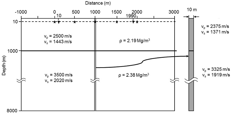
Synthetic model used for this seismic reflection interferometry (SRI) study. Seismic energy independently generated at five sources (stars) at 10 m depth was assumed to be recorded at 99 active receivers (triangles) buried at the same depth as the sources. The 10-m thick vertical boundary (gray) in the middle of the profile is horizontally exaggerated and illustrated at the right of the model.
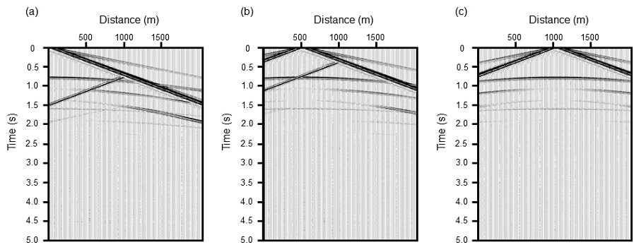
지진파 탄성모델은 시간 간격 0.2 ms, 수평 및 수직 공간 간격 모두 1.25 m인 표준격자를 사용하여 5 s까지 유한차분법으로 계산하였다. 파원은 수직방향으로 작용하는 (0, 0, 1) 형태의 점원(point source)으로 우세주파수가 20 Hz인 영위상(zero-phase) 리커(Ricker) 파형요소를 사용하였다. 파원의 위치는 좌측경계로부터 1,000 m 떨어진 원점(0 m)부터 2,000 m까지 구간에 500 m 간격의 5개 지점에서 깊이 10 m에 설정하였고, 서로의 간섭이 없도록 독립적 발파를 가정하였다. 또한 수신기는 10 m부터 1,990 m까지 20 m 간격으로 99개의 수직 지오폰이 파원과 같은 깊이인 10 m에 매설된 상황을 모의하였다. 그림 3은 파원이 원점거리 0, 500, 1,000 m에 있는 5 s 길이의 공발점(혹은 공통발파점, common source gather) 자료를 보여주며, 1,500과 2,000 m에서의 공발점 자료는 측선 중앙부인 1,000 m 지점을 기준으로 각각 500 m와 0 m 공발점 자료의 대칭형태가 된다.
4. 자료처리
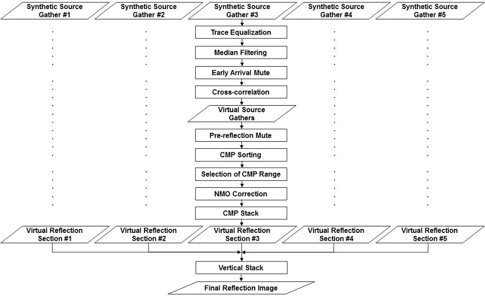
합성지진파 자료로부터 가상지진파 영상을 작성하기 위하여, 트레이스 균등화, 메디안 필터링, 초기뮤트, 상호상관 등의 가상공발점 자료작성을 위한 1차 처리과정과 뮤트, 공중점 분류, 공중점 범위선택, 수직경로시차(normal moveout) 보정, 수평중합, 수직중합 등 통상적 반사파 자료처리 단계들로 구성된 2차 처리과정을 거쳤다(그림 4). 2차원 모델의 경우, 레일리파는 기하학적 감쇠를 일으키지 않으나, 파원이 점원(point source)인 경우 기하학적 감쇠가 일어난다. 주시 증가에 따른 진폭감소 현상은 일반적으로 주시에 비례하는 이득조절(gain control)을 적용하여 보정하는데, 이 자료의 경우에는 직접 전파하는 레일리파의 거리에 따른 진폭 감쇠를 트레이스 균등화를 통하여 보정함으로써, 이득조절 효과도 동시에 달성하였다(그림 5a). 이어서 직접 전달되거나(R) 모델 중앙에 위치한 수직경계면에서 회절된 레일리파(RdR)의 최대진폭 위치에 중심을 둔 창길이 0.1 s인 메디안 필터를 통해 레일리파 에너지를 대폭 감소시켰다(그림 5b). 이 창길이는 우세주파수가 20 Hz이므로, 파원의 자기상관함수 ΦS(t)의 길이, 즉, 파원 주기의 2배가 되도록 결정하였다.
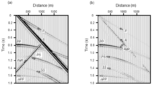
Synthetic source gathers (SSGs) (a) before and (b) after applying the median filter. Strong linear events comprise both direct P (P) and R (R) waves with positive slopes, and diffracted R (RdR) waves with a negative slope. Reflections of P (P`P´), converted (P`S´), and S (S`S´) waves are hyperbolic. After applying the median filter (b), however, both direct and diffracted R waves were greatly attenuated.
이 후, 모든 트레이스 쌍의 조합에 대해 상호상관을 실시하여 가상공발점 자료를 생산하였다(그림 6). 가상파원이 합성파원으로부터 가까운 경우는 합성공발점 자료와 비슷한 모습을 보이나(그림 6a), 떨어져 있는 경우에는 근거리 트레이스의 값들이 모두 영(0)으로 나타나 있다(그림 6b). 이는 능동식 지진파 간섭법에서는 상호상관 트레이스 쌍을 이루는 수신기 중에서 파원으로부터 먼 거리의 수신기가 반사파 가상파원이 될 수 없기 때문이다(그림 1). 그러나 파원의 위치가 고루 분포하는 것을 가정하는 배경잡음을 이용한 수동식 지진파 간섭법에서는 모든 트레이스 쌍의 상호상관을 구하여야 한다.
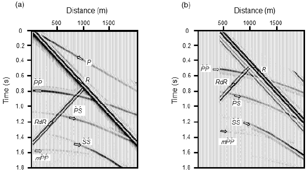
Virtual source gathers without the preprocess for attenuating non-reflection events at (a) the nearest active receiver location and (b) a distance of 410 m from the origin. The near-offset traces (at distances less than 30 m) in (b) are null since the farther receivers of the receiver pairs can not serve as virtual sources.
상호상관으로 구한 가상공발점 자료를 공중점으로 분류한 후, 모델의 상부층 P파 속도인 2,500 m/s의 등속도로 수직경로시차를 보정하였고, 이어서 수평중합을 실시하였다. 물론 사전에 속도를 모르는 능동적 탐사자료의 경우에는 수직경로시차를 이용한 통상적 속도분석이나, 음파검층, 수직탄성파, 굴절파 탐사 등에서 얻은 결과를 이용하여 속도정보를 구하여야 할 것이다. 또한 수신기들이 불규칙하게 놓인 수동적 방법을 적용할 경우는 공간자기상관함수(spatial autocorrelation; Aki and Richard, 2002) 역산이나 원거리 지진자료를 이용한 수신함수(receiver function; e.g., Chang and Baag, 2007) 등의 방법으로 속도정보를 구할 수 있다. 이러한 모든 처리과정을 5개 합성파원 자료에 독립적으로 동일하게 적용하였으며, 그 결과 구해진 수평중합자료(그림 7) 중에서 불변위상 공중점 자료만을 수직중합하여 최종 가상반사파 영상을 작성하였다(그림 8a).
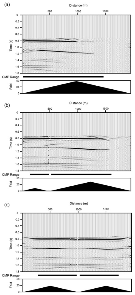
Virtual stacked sections using the common source gathers where the synthetic sources are at (a) 0, (b) 500, and (c) 1000 m distances, respectively. The corresponding CMP ranges for the vertical stack are (a) 20-1470, (b) 140-480 and 520-1610, and (c) 280-980 and 1020-1720 m, respectively, which were determined based on the stationarity of phase. Both the CMP ranges (thick bars) and folds (filled curves) are illustrated below each sections.
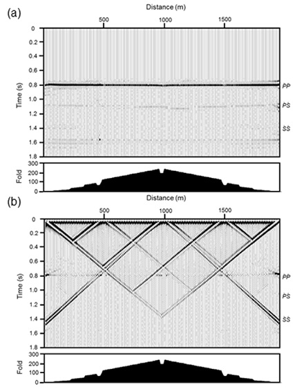
Virtual stacked sections (a) with and (b) without the processing steps for attenuation of non-reflection events. Non-reflection dipping events are apparent in (b) even after the 5-fold vertical stack. The dipping events have absolute apparent velocities close to 700 m/s, which are slightly higher than half of the surface R-wave velocity. The CMP folds are illustrated below each stack sections.
5. 관찰 및 분석
이득보정과 트레이스 균등화를 마친 공발점 자료(그림 5a)는 P파(P)와 레일리파(R)가 원점을 지나는 직접파로 나타나 있으며, , , (Aki and Richard, 2002) 일차반사파와 P파 다중반사파(m)는 1번 채널에서 각각 0.80, 1.08, 1.37, 1.60 s 부근부터 주시가 쌍곡선 형태로 증가하는 모습을 보인다. 각각 벌림(offset)이 중거리와 원거리에서 진폭이 큰 와 반사파와는 달리 반사파는 근거리에서 강하고 벌림 증가에 따라 감소하는 AVO (Amplitude Variation with Offset) 특성을 보인다. 또한 수직경계면에서 회절된 레일리파(RdR)는 표층의 레일리파 속도인 약 1,350 m/s 정도로 음(-)의 기울기를 갖고 있다.
R파는 트레이스 균등화 과정 후에 트레이스별로 진폭이 거의 일정하며 반사파들보다 월등히 큰 특성을 보인다(그림 9). 5개 합성파원 위치에 따라 다소 변화는 있으나, 복소트레이스 분석법(complex trace analysis; Taner et al., 1979)으로 구한 포락선 최대진폭의 트레이스별 평균은 R파가 전체 합의 94% 이상을 차지하며, RdR, , P, , , 순으로 감소한다(표 1). 즉 보다 진폭이 60배 이상 강하며, RdR 위상까지 포함하면 레일리파가 96% 이상을 차지한다. 정작 가상반사파 자료를 구하는데 사용하는 및 위상은 각각 1.6%와 0.3%로 매우 약하므로 이 두 위상의 상호상관 계수는 당연히 극히 작아지게 된다. 이러한 진폭의 차이가 그동안 가상반사파 영상법이 실용화되지 못했던 주요 원인임을 명확하게 지시한다.
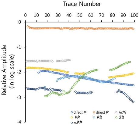
Instantaneous amplitudes of various phases in the synthetic seismic data for the source at the origin. Notice that the vertical axis is in the logarithmic scale. Direct R wave (orange circles) is much stronger than the P`P´ reflection (yellow circles) event.

Maximum instantaneous amplitudes of various seismic phases in the five synthetic common-source-gathers (CSGs) before and after application of both the median filtering and pre-reflection mute.
따라서 가상반사파 영상의 품질향상을 위한 첫 단계는 일반 반사파 자료처리와 마찬가지로, R 및 RdR 위상의 레일리파를 상호상관 과정 이전에 제거하거나 최대한 감쇠시켜서 그 영향을 최소화해야 하는 것이다. 반사파 탐사 시에 레일리파는 가장 성가신 잡음으로, 이를 최대한 억제하기 위해서 자료획득 과정에서는 수신기군(receiver array), 파원군(source array), 매설파원(burried source) 등의 방법을 적용하고, 처리과정에서는 일반적으로 주파수 필터(frequency filter), 주파수-파수 필터(f-k filter), 라돈필터(Radon filter), 분극필터(polarization filter), 공간예측 곱풀기(spatial predictive deconvolution) 등의 필터를 적용한다(Yilmaz, 2008). 그러나 이 합성자료의 경우는 워낙 레일리파 에너지가 강하고, 반사파와의 주파수 차이가 크지 않으며, 공간 알리아싱 등으로 인하여 주파수 필터나 주파수-파수 필터를 적용해도 모두 성공적이지 못하였다. 또한 분극필터는 수직성분만을 사용하여서 적용할 수 없었다.
수직탄성파자료의 일관성 잡음(coherent noise)인 하향파 제거(Duncan and Beresford, 1995; Hinds et al., 1996)에 사용된 바 있는 메디안 필터를 파형이 거의 일정한 레일리파 제거에 적용했을 때 상당히 효과적인 결과를 얻은 바 있다(Song et al., 2018). 이 자료에 대해서도 창길이 100 ms의 메디안 필터를 R 및 RdR 위상에 적용한 후에는 위상의 트레이스 평균 진폭이 상대적으로 월등히 강화되었다(그림 5b). 추가적으로 반사파 도달 이전의 지진파 신호들을 초기뮤트로 제거한 이후에는 위상의 상대진폭이 무려 10배 이상 증가하였고 R 위상은 60% 이상 감쇠되었다(표 1). 메디안 필터와 초기뮤트를 적용하지 않고 구한 중합영상(그림 8b)에는 겉보기 속도 700 m/s정도의 매우 강한 경사 이벤트가 존재한다. 이는 상부층에서의 레일리파 속도의 절반보다 약간 큰 속도로, 파원과 수신기의 기하학적 배치에 따라 발생하는 지진파 간섭법의 고유한 처리잡음이다(Song et al., 2018). 메디안 필터와 초기뮤트를 모두 적용한 결과(그림 8a)와 비교할 때, 이 R 및 RdR 위상 제거를 위한 처리과정의 중요성은 자명하다.
앞의 이론부분에서 설명하였듯이 파원에서 R1까지의 거리(Xsr)와 수신기 간격(Δx)이 같을 때(i.e., Xsr = Δx), 지표면 1차 다중반사파를 사용하는 반사파 간섭법에서는 가상중앙점(virtual midpoint)이 파원(Sr)으로부터 수신기(R1)까지 거리의 1.5배 되는 곳에 위치한다(그림 1). 일반적으로 가상중앙점의 위치(XM)는 파원에서 수신기 R1까지의 거리(Xr)에 수신기 간격(Δx)의 절반을 더한 거리가 된다, 즉,
| (2) |
파원이 원점거리 0 m에 있는 첫 번째 합성공발점 자료의 경우는(그림 3a) Xsr = 10 m 이고 Δx = 20 m로 서로 일치하지 않음으로, 첫번째 수신기와 2번째 수신기가 정확히 불변위상 위치에 놓이지 않는다. 그러나 1차 프레넬 대역 안에 놓여서 보강간섭이 일어나므로, 가상반사파 신호를 이용할 수 있다. 파원에서 가장 가까운 공중점의 위치는 첫 번째 파원으로부터 20 m, 즉 원점거리 20 m가 된다. 또한 파원에서 가장 먼 공중점은 Xsr = Δx = 980 m으로, 원점거리 1,470 m가 된다(그림 7a). 파원으로부터 대략 1,000 m 이내의 공중점에서는 반사면이 잘 영상화되어 있으나, 불변위상 조건을 만족시키는 최대 거리인 1,470 m 부근에서는 반사 이벤트의 신호대-잡음비가 매우 낮은 양상을 보인다. 이는 앞에서 기술한 바와 같이, 불변위상 파원은 파원에서 가까울수록 밀도가 높게 분포하는데 그 원인이 있다.
유사하게 파원이 원점거리 500 m에 있는 2번째 합성공발점 자료(그림 3b)의 경우도, 파원에서 가장 가까운 공중점의 위치는 파원으로부터 ±20 m가 되어 원점거리 480 m와 520 m가 된다. 또한 왼쪽의 가장 먼 공중점 위치는 Xsr = Δx = 240 m일 때, 파원으로부터 -360 m 지점인 원점거리 140 m가 되며, 오른쪽의 가장 먼 공중점 위치는 Xsr = Δx = 740 m일 때, 파원으로부터 +1,110 m 지점인 원점거리 1,610 m가 된다(그림 7b). 파원이 원점거리 1,000 m에 있는 3번째 합성공발점 자료(그림 3c)의 경우도, 파원에서 가장 가까운 공중점의 위치는 파원으로부터 ±20 m가 되어 원점거리 980 m와 1,020 m가 된다. 또한 가장 먼 공중점 위치는 Xsr = Δx = 480 m일 때, 파원으로부터 ±720 m가 되어, 원점거리 280 m와 1,720 m가 된다(그림 7c). 이는 중앙점 범위가 측선 길이의 1/2 정도인 통상적인 반사파탐사의 경우와는 달리, 1.5배 가량 넓어짐을 보인다. 파원이 1,500 m와 2,000 m에 있는 4번째와 5번째 합성공발점 자료의 경우는 당연히 각각 2번째와 1번째 합성공발점 자료의 대칭 형태가 된다.
그 밖의 고려할 사항으로, 파원의 주파수 성분에 따른 수평분해능, 회절파의 영향, 반사각에 따른 반사계수 변화 등이 있다. 불변위상법의 보강간섭 범위를 1차 프레넬(Fresnel) 대역 반경으로 계산하면 파원별로 최대 360~375 m이 되며, 파선방향을 고려하면 중합에 사용할 수 있는 공중점 범위는 더 넓어져서 최대 371~530 m이 된다. 그러나 파원이 유한한 주파수 범위를 가짐으로, 1차 프레넬 대역의 중심에서 가장자리 쪽으로 접근할수록 진폭감소와 회절현상이 발생하게 되고 이로 인하여 반사영상의 품질이 저하되는 점도 함께 고려할 필요가 있다. 또한 신호대-잡음비가 낮은 실제 자료의 경우에는 중첩도가 높은 공중점 자료만을 취할 필요도 있다.
6. 결론
수직 단층대가 존재하는 수평 2층구조 모델을 대상으로 작성한 합성지진파 자료를 이용하여 가상반사파 영상 작성시 유의할 점을 분석하였다. 분석결과는 직접전달 및 회절된 레일리파의 진폭이 반사파 진폭보다 평균 60배 이상 강하며, 가상 반사파 신호를 구하는데 사용되는 와 위상의 상대진폭이 각각 1.3%와 0.2%로 매우 약한 점이 가상반사파 영상법이 실용화되지 못하고 있는 주요 원인임을 보여주었다. 따라서 상호상관 처리과정 이전에 R 및 RdR 위상의 감쇠는 필수적이다. 추가적으로 반사파 이전 지진파 신호들을 초기뮤트로 제거한 이후에는 위상의 상대진폭이 무려 10배 이상 증가하였고 R 위상은 60% 이상 감쇠되었다.
또한 불변위상 특성을 고려할 때, 지표면 1차 다중반사파를 사용하는 반사파 간섭법에서 가상중앙점의 위치는 파원으로부터 상호상관 트레이스 쌍의 첫 번째 수신기까지 거리와 상호상관 수신기 간격의 절반을 더한 곳이다. 이러한 가상중앙점 위치를 기준으로 수평중합할 공중점 범위를 정하여야 하며, 불변위상 파원 밀도가 파원 주변에서 높은 점과 자료에 따라 반사파 진폭이 큰 공중점 범위도 고려 대상에 포함시켜야 한다. 그밖에 유한한 주파수 성분을 갖는 실제 파원들의 수평분해능도 함께 감안하여야 한다.
Acknowledgments
이 논문은 기상청 지진기술개발사업(KMIPA2015-7010)과 2019년도 정부(교육부)의 재원으로 한국연구재단의 지원을 받아 수행된 기초연구사업(No.2019R1A6A1A03033167)에서 지원받았음을 밝힙니다. 아울러 2018년도 강원대학교 대학회계 연구비의 지원도 받아서 수행하였습니다. 또한 이 논문은 2019년도 정부(산업통상자원부)의 재원으로 한국에너지기술평가원의 지원을 받아 수행된 연구(No.20194010201920, 탄성파와 전자탐사자료 복합역산을 통한 정밀탐사 GET-Future 연구실)임을 밝힙니다. 저자 중, 송영석은 한국연구재단의 글로벌박사양성사업(NRF-2017H1A2A1044244-Global Ph.D. Fellowship program)에 의해 지원받았습니다.
References
-
Abe, S., Kurashimo, E., Sato, H., Hirata, N., Iwasaki, T. and Kawanaka, T., 2007, Interferometric seismic imaging of crustal structure using scattered teleseismic waves. Geophysical Research Letter, 34.
[https://doi.org/10.1029/2007GL030633]

- Aki, K. and Richard, P.G., 2002, Quantitative seismology. 2nd ed., University Science Books, 685 p.
-
Bolshakov, O.A., Patterson, D.J. and Lan, C., 2011, Deep fracture imaging around the wellbore using dipole acoustic logging. In SPE Annual Technical Conference and Exhibition (Expanded Abstracts), October 30 - November 2, Denver, Colorado, USA, SPE 146769.
[https://doi.org/10.2118/146769-MS]

-
Calvert, R.W., Bakulin, A. and Jones, T.C., 2004, Virtual sources, a new way to remove overburden problems. In 66th EAGE Conference & Exhibition (pp. cp-3), European Association of Geoscientists & Engineers, (Extended Abstracts).
[https://doi.org/10.3997/2214-4609-pdb.3.P234]

-
Campillo, M. and Paul, A., 2003, Long-range correlations in the diffuse seismic coda. Science, 299, 547-549.
[https://doi.org/10.1126/science.1078551]

-
Chang, S.-J. and Baag, C.-E., 2007, Moho Depth and Crustal Vp/Vs Variation in Southern Korea from Teleseismic Receiver Functions: Implication for Tectonic Affinity between the Korean Peninsula and China. Bulletin of the Seismological Society of America, 97, 1621-1631.
[https://doi.org/10.1785/0120050264]

-
Cho, K.H., Herrmann, R.B., Ammon, C.J. and Lee, K., 2007, Imaging the upper crust of the Korean peninsula by surface-wave tomography. Bulletin of the Seismological Society of America, 97, 198-207.
[https://doi.org/10.1785/0120060096]

-
Claerbout, J., 1968, Synthesis of a layered medium from its acoustic transmission response. Geophysics, 33, 264-269.
[https://doi.org/10.1190/1.1439927]

- Clayton, R.W. and Engquist, B., 1977, Absorbing boundary conditions for acoustic and elastic wave equations. Bulletin of the Seismological Society of America, 67, 1529-1540.
-
Duncan, G. and Beresford, G., 1995, Median filter behaviour with seismic data 1. Geophysical Prospecting, 43, 329-345.
[https://doi.org/10.1111/j.1365-2478.1995.tb00256.x]

-
Grechka, V. and Zhao, Y., 2012, Microseismic interferometry. The Leading Edge, 31, 1478-1483.
[https://doi.org/10.1190/tle31121478.1]

-
Hinds, R.C., Anderson, N.L. and Kuzmiski, R.D., 1996, VSP Interpretive Processing: Thaeory and Practice. Open File Publications No. 3, Society of Exploration Geophysicists, 204 p.
[https://doi.org/10.1190/1.9781560801894]

-
Kang, T.S. and Shin, J.S., 2006, Surface-wave tomography from ambient seismic noise of accelerograph networks in southern Korea. Geophysical Research Letters, 33.
[https://doi.org/10.1029/2006GL027044]

- Kim, K.Y., Park, I.S. and Byun, J.M., 2018, Characteristics of virtual reflection image in seismic interferometry using synthetic seismic data. Geophysics and Geophysical Exploration, 21, 94-102 (in Korean with English abstract).
-
Kuperman, W.A. and Ingenito, F., 1980, Spatial correlation of surface generated noise in a stratified ocean. The Journal of the Acoustical Society of America, 67, 1988-1996.
[https://doi.org/10.1121/1.384439]

-
Ruigrok, E., Campman, X. and Wapenaar, K., 2011, Extraction of P-wave reflection from microseisms. Comptes Rendus Geoscience, 343, 512-525.
[https://doi.org/10.1016/j.crte.2011.02.006]

-
Schuster, G.T., 2009, Seismic Interferometry. Cambridge University Press, 274 p.
[https://doi.org/10.1017/CBO9780511581557]

-
Shapiro, N.M., Campillo, M, Stehly, L. and Ritzwoller, M., 2005, High-resolution surface-wave tomography from ambient seismic noise. Science, 307, 1615-1618.
[https://doi.org/10.1126/science.1108339]

-
Snieder, R., 2004, Extracting the Green’s function from the correlation of coda waves: A derivation based on stationary phase. Physical Review E, 69.
[https://doi.org/10.1103/PhysRevE.69.046610]

- Song, Y.S., Kim, K.Y., Park, I.S., Byun, J.M. and Lee, J.W., 2018, Preliminary image of upper mantle structure beneath the Korean Peninsula by cross-correlation of seismic noise data. In EGU General Assembly Conference, (Abstracts), Vienna, Austria, p. 6034.
-
Taner, M.T., Koehler, F. and Sheriff, R.E., 1979, Complex seismic trace analysis. Geophysics, 44, 1041-1063.
[https://doi.org/10.1190/1.1440994]

-
Van Kampen, N.G., 1958, The method of stationary phase and the method of Fresnel zones. Physica, 26, 437-444.
[https://doi.org/10.1016/S0031-8914(58)95919-6]

-
Wapenaar, K., Draganov, D., Snieder, R., Campman, X. and Verdel, A., 2010, Tutorial on seismic interferometry: Part 1 - Basin principles and applications. Geophysics, 75, 75A195-75A209.
[https://doi.org/10.1190/1.3457445]

-
Wapenaar, K., Draganov, D., Thorbecke, T. and Fokkema, J., 2002, Theory of acoustic daylight imaging revisited. 2002 SEG Annual Meeting (Expanded Abstracts), October 6-11, Salt Lake City, Utah, 2269-2272.
[https://doi.org/10.1190/1.1817165]

- Yilmaz, Ö., 2008, Seismic Data Analysis (I): processing, inversion, and interpretation of seismic data. Society of Exploration Geophysicists, 1000 p.

