
자연의 변형조직을 그대로 보존한 단층비지의 전단실험
초록
자연 단층비지의 변형조직은 단층의 마찰강도를 약화시키는 중요한 요인 중 하나로 알려져 있다. 그러나 그 변형조직이 단층비지의 다양한 마찰특성에 미치는 영향을 이해하기 위한 연구는 거의 수행된 바가 없다. 본 연구에서는 변형조직 훼손을 최소화하면서 자연 단층비지를 채취할 수 있는 장비를 제작하고 그것을 통해 얻은 시료(웨이퍼 시료)와 기존 방식으로 준비된 시료(물로 포화된 분말 시료 및 반죽 시료)를 대상으로 예비 전단실험을 각각 실시하여 그 결과를 비교해 보았다. 마찰계수 측정결과, 웨이퍼 시료에서 가장 낮은 마찰계수(~0.25)가 측정되었고, 반죽 시료(~0.3), 물로 포화된 분말 시료(0.3-0.4) 순으로 마찰계수의 차이가 확인되었다. 마찰-속도 파라미터(a – b)와 마찰회복률의 경우 모든 시료가 안정한 미끌림과 관련된 속도강화 거동(a – b > 0)과 거의 0에 가까운 마찰회복률을 보였으나, 웨이퍼 시료의 경우 가장 낮은 a – b 값과 음의 마찰회복률을 갖는 등 다른 시료와는 구별되는 특성을 보였다. 이러한 예비실험 결과는 자연의 변형조직이 단층의 미끌림에 미치는 영향이 기존의 연구에서 보고된 단층의 전단강도 측면뿐 아니라 마찰안정성 등 보다 다양한 측면으로 작용할 수 있음을 시사한다.
Abstract
Deformation fabrics developed in natural fault gouges are one of the critical factors leading to fault weakness. However, the possible effects of the deformation fabrics on various frictional properties of fault rocks have been almost unexplored. In this study, we developed new equipment for taking intact gouges in a wafer form, conducted preliminary shear tests on the wafer specimen, and compared the experimental results from the wafer specimen with those from other gouge specimens (water-saturated and paste specimens) that were prepared in the conventional methods. For the friction coefficient, the wafer specimen showed the lowest value (~0.25), while the paste and saturated specimens showed ~0.3 and 0.3-0.4, respectively. For the frictional stability and frictional healing, all the gouge specimens showed velocity-strengthening (a – b > 0) behavior, which is related with an intrinsically stable fault slip, and very low (nearly zero) healing rate. It is noteworthy that the wafer specimen showed the lowest a – b value and negative healing rate. The preliminary results indicate that the deformation fabrics may affect not only frictional strength but also other critical mechanical properties (e.g., frictional stability) of faults.
Keywords:
fault gouge, shear tests, deformation fabrics, fault gouge sampler, frictional properties키워드:
단층비지, 전단실험, 변형조직, 단층비지 채취기, 마찰특성1. 서 론
단층암의 마찰특성에 대한 역학적인 연구는 단층의 미끌림 거동과 지진의 발생 메커니즘을 이해하는데 있어 필수적이다(Morrow et al., 1992; Marone, 1998a; Saffer and Marone, 2003; Carpenter et al., 2009; Collettini et al., 2009; Haines et al., 2009; Ikari et al., 2009, 2011; Faulkner et al., 2010; Smith and Faulkner, 2010; Moore and Lockner, 2011; Smith et al., 2017). 자연 단층의 전단강도(마찰강도)와 관련하여, 가령 북미의 산안드레아스 단층의 일부가 매우 낮은 전단강도를 보임은 그 단층암이 마찰강도가 매우 낮은 광물로 이루어져 있는 것 때문으로 생각되며(Holdsworth, 2004; Carpenter et al., 2012), 단층비지 내부에서 과유체압 상태가 발달하는 경우에도 자연 단층의 전단강도가 실험실에서 측정된 마찰강도보다 훨씬 낮은 값을 가질 수 있음이 보고되었다(Blanpied et al., 1992; Scuderi and Collettini, 2016). 이러한 연구들에서는 일반적으로 자연 단층시료를 채취하여 실험실에서 건조 및 파쇄 과정을 통해 준비한 분말 시료를 실험의 초기 물질(starting material)로서 사용하였다. 이러한 방식의 경우, 자연 단층물질을 실험에 사용하는 것이긴 하지만 자연 단층암의 변형조직이 파괴되는 단점이 있다. 자연 단층의 변형조직이 단층의 역학적 거동에 영향을 미칠 수도 있음을 제안한 기존의 연구들을 고려한다면(Faulkner et al., 2003; Smith et al., 2011), 단층암의 변형조직을 보존하는 방식의 체계적인 실험 연구가 필요하다고 하겠다. 이와 관련하여, 다음의 두 선행연구결과는 주목할 필요가 있다. Collettini et al. (2009)는 이탈리아의 Zuccale 단층에서 훼손을 최소화하는 방식의 단층암 시료(wafer; 이하 웨이퍼 시료)를 준비하여 전단실험을 실시하였고, 그 단층의 전단강도가 낮을 수 있는 이유는 단층암의 엽리조직의 발달 때문인 것으로 보고하였다. 또한 Smith et al. (2017)도 뉴질랜드의 Moonlight 단층대에서 엽리조직을 그대로 보존한 단층암을 채취하여 이를 실험에 사용함으로써 그 단층이 낮은 마찰강도를 가짐을 보고한 바 있다. 그러나 위의 연구들은 자연 단층암의 변형조직이 마찰강도에 미치는 영향만을 살펴 본 것이어서, 미끌림이 개시된 이후 비지진성 혹은 지진성 미끌림 거동을 보일 것인지에 대한 마찰안정성(frictional stability) 측면과 단층이 정지상태 후 다시 재활될 시에 방출되는 응력과 관련된 마찰회복률(frictional healing) 측면에 단층암 변형조직이 미치는 영향에 대해서는 고려하지 않았다. 따라서 본 연구에서는 자연 단층암의 변형조직이 여러 마찰특성에 어떠한 영향을 미치는지에 대한 체계적인 실험 연구가 필요하다는 문제의식 하에, 우선적으로 자연 단층비지를 그대로 채취할 수 있는 장비를 개발하였으며, 이를 통해 얻은 웨이퍼 시료와 기존의 방식대로 준비한 두 시료(물로 포화된 분말 시료와 반죽 시료) 등 서로 다른 세가지 유형의 시료에 대해 저속전단실험을 예비적으로 실시하여 그 결과를 비교해보고자 하였다.
2. 단층비지 채취장비 및 채취방법
연구 대상은 포항시 보경사 인근에 위치한 양산단층의 손상대에 발달한 부차단층(Kim et al., 2016; Woo et al., 2016)으로, 석영과 장석이 우세한 사암과 이암이 교호하는 퇴적암을 가로지르며 발달한 단층이다(그림 1a). 단층핵에는 약 1-2 cm 폭으로 엽리상의 암녹색 점토질 단층비지가 발달하며 단층면의 자세는 N41°E/52°NW 이다(그림 1b, 1c). 본 연구에서는 자연 단층비지의 변형조직 및 유체 보유상태 등의 특성을 보존시킨 시료 즉, 훼손을 최소화한 자연 상태 그대로의(in-situ) 단층비지(intact fault gouge)를 얻기 위하여 단층비지 채취기(fault gouge sampler)를 제작하였다(그림 2a, 2b). 이 채취기는 야외에서 휴대할 수 있는 크기로 폭과 높이가 각각 8 cm와 18 cm이고, 시료를 채취하는 과정에서 단층비지 내에 분포하는 암편과 같은 강한 물질에 의한 장비의 변형을 막기 위하여 고강도 스테인레스 304(SUS 304)로 제작하였다. 단층비지 시료 채취 방법은 다음과 같다: (1) 야외 단층 노두에서 단층비지를 수 cm 두께의 판(plate) 형태로 떼어낸다. (2) 채취기에서 시료 회수함(그림 2, 6번)을 빼낸 후 판 형태의 단층비지의 엽리면 상에 올려놓고 눌러서 그 안에 단층비지가 채워지도록 한다(그림 1c). 시료 회수함의 아래면을 이루는 네 모서리는 쐐기형태로 만들어서 시료 회수함으로 인한 단층비지의 변형을 줄임과 더불어 단층비지가 쉽게 관통되도록 제작하였다(그림 2c). (3) 시료 회수함을 채취기에 장착한 후, 커버(그림 2, 7번)를 덮고, 피스톤 푸셔(piston pusher; 그림 2, 1번)를 돌려 시료 회수함 안에 있는 단층비지가 커버에 맞닿을 때까지 위쪽 방향으로 배출시킨다. 커버가 열리지 않게 손으로 막은 후, 단층비지를 위로 상승시키면서 약간의 압축 과정을 통해 시료 회수함 안에 있는 단층비지의 빈 공간을 채우도록 한다. (4) 다음으로, 커버를 열고 피스톤 푸셔를 돌려 단층비지 시료를 조금씩 위로 배출시킨다. 이때 디지털 게이지(그림 2, 2번)를 이용하여 실험에 사용할 단층비지의 두께(~2 mm)로 배출시킨 후, 0.15 mm 두께의 스테인레스 재질인 커팅 와이어(그림 2, 5번)를 커터 레일(그림 2, 4번)을 따라 밀어줌으로써 시료를 얇은 판 형태(웨이퍼)로 잘라낸다(그림 2d). 회수한 웨이퍼 시료는 야외에서 즉시 휴대용 진공포장기로 밀봉하여 자연의 수분상태 그대로 보존시킨다(그림 2e).
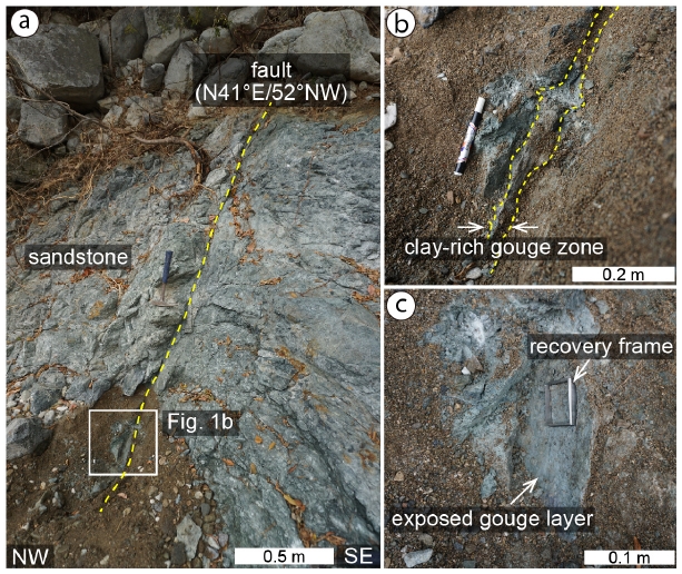
(a) Outcrop photograph of the NE-striking, subsidiary fault developed in sandstone in the damage zone of the Yangsan fault, Bogyeongsa area. (b) Close-up view of the boxed area in (a) where the gouge specimens (powder and wafer) were taken. A narrow (~2 cm in width) clay-rich gouge zone is observed in the core of the fault. (c) Side view of the fault surface exposed after the removal of the wall rock. The recovery frame was pushed into the gouge layer to collect the wafer specimens.
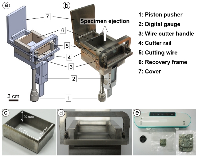
Illustration (a) and photograph (b) of the fault gouge sampler. (c) Bottom side of the recovery frame. Note the wedge-shaped bottom designed for easy penetration through fault gouge. (d) Close-up view of the wire cutter handle and cutting wire. (e) Portable vacuum packaging machine. It is used for vacuuming and sealing a plastic pack where a gouge specimen is kept with original water content.
3. 예비 실험
3.1 실험방법
훼손을 최소화시킨 자연 단층비지(웨이퍼 시료)와 전처리 과정을 거친 분말 시료의 마찰특성을 비교하고 이해하기 위해 다음의 세 가지 방법으로 시료를 준비하였다: (1) 야외에서 채취한 단층비지 시료를 60℃에서 하루 동안 건조 한 후, 마이크로나이징 밀(micronizing mill)을 이용하여 5분 동안 분쇄, 이후 #80체를 이용한 체거름을 통해 125 µm 이하의 분말을 회수하고 모세관 현상을 통해 1시간 동안 물로 포화시킨 시료(saturated powder; 이하 물로 포화된 분말 시료; 그림 3a), (2) 자연 단층비지가 갖는 찰흙과 유사한 점착성을 재현하기 위하여 (1)과 동일한 과정으로 회수한 분말 시료를 증류수와 5:1 비율(20 wt%)로 혼합하여 반죽 형태로 제작한 시료(paste; 이하 반죽 시료; 그림 3b), 그리고 (3) 단층암 시료채취기를 통해 자연의 변형조직과 유체 보유상태를 보존시키면서 채취한 웨이퍼 시료(그림 3c). 이상 세 가지 유형의 시료를 각각 측면블록(4×5×2 cm) 2개와 중앙블록(4×8×2 cm) 사이에 2 mm 두께의 샌드위치 레이어 형태로 채움으로써 시료결합체(specimen assembly)를 준비한 후 이를 전단실험에 이용하였다(그림 3d). 시료결합체에 사용한 암석은 전라북도 익산에서 산출되는 쥐라기 황등화강암이며, 전단면으로 사용될 암석면은 결합에 앞서 #80 실리콘 카바이드를 이용하여 연마함으로써 암석블록과 단층비지의 경계면을 따라서만 미끌림이 발생되지 않고 시료 내부에서도 미끌림이 발생할 수 있도록 유도하였다(Marone et al., 1990). 모든 전단실험은 한국지질자원연구원에서 보유 중인 저속전단시험기(low-velocity double direct shear test apparatus, DDST)를 이용하여 실시하였다(Woo et al., 2015 참조).
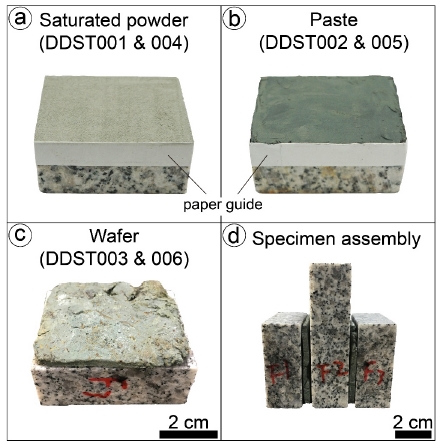
Three types of specimens used for the double direct shear tests. (a) Saturated powder specimen layer on a side block of granite. (b) Paste layer. (c) Wafer. (d) Specimen assembly in which two layers of the gouge specimens are sandwiched between a long central block of granite and two shorter side blocks of granite.
전단실험은 전체적으로 속도 단계 실험(velocity stepping test, 이하 VS 실험)과 미끌림-정지-미끌림 실험(slide-hold-slide test, 이하 SHS 실험) 순으로 진행하였다(그림 4). VS 실험은 전단 속도를 변화시키는 실험 방식으로(본 연구에서는 3-30-3 µm/s 사용), 물질의 마찰안정성을 측정하여 단층물질의 미끌림이 개시된 이후 단층이 느리고 안정하게 미끌릴지 혹은 급격한 마찰강도의 약화로 빠르고 불안정하게 미끌릴지를 정량적으로 해석하기 위한 실험 방법이다(Dieterich, 1979; Ruina, 1983; Marone, 1998a; Woo et al., 2015, 2016). 전단속도를 갑작스럽게 증가(감소)시킴에 따라 마찰계수가 기존의 정상상태(steady state) 값으로부터 즉각적으로 증가(감소)하는 특성을 기술하는 계수를 “a”, 증가(감소)한 마찰계수가 시간과 미끌림에 따라 진화하여 새로운 정상상태에 도달하는 특성을 기술하는 계수를 “b”라고 하면, 마찰강도의 속도의존성을 표현하는 마찰-속도 파라미터(friction-rate parameter or velocity-dependence parameter)인 a – b는 다음의 식으로 표현된다.
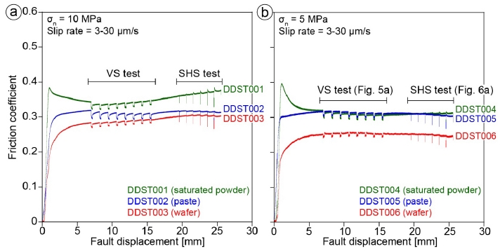
Comparison of frictional behaviors of three types of specimens (saturated powder, paste, and wafer). In each test, a series of velocity stepping tests (VS tests) and slide-hold-slide tests (SHS tests) were conducted after the friction coefficient reaches a steady state. (a) Experimental results at a normal stress of 10 MPa. The saturated powder and wafer specimens show the highest and the lowest friction coefficients, respectively. (b) Experimental results at a normal stress of 5 MPa. Note much lower friction coefficient of the wafer specimen than those of the saturated powder and paste specimens.
| (1) |
여기서 µss와 V는 각각 정상상태 마찰계수와 전단속도이다. 양의 속도의존성(a – b > 0)은 속도 강화(velocity strengthening)를 지시하고, 이는 단층물질이 안정한 미끌림 거동을 보일 것임을 의미한다. 음의 속도의존성(a – b < 0)은 속도 약화(velocity weakening)를 지시하고 이는 단층의 불안정한 지진성 미끌림의 필요조건이 된다.
SHS 실험은 일정한 전단속도(30 µm/s)로 진행하던 전단미끌림을 일정 시간(3, 10, 30, 100, 300, 1000 초)동안 정지상태로 유지시키다가 다시 동일한 전단속도로 미끌리는 방식으로 진행한다. 이때 전단미끌림 시 관찰되는 동적마찰계수(dynamic friction coefficient)와 정지 후 재전단(re-shear) 시 관찰되는 정적마찰계수(static friction coefficient)의 차이를 Δµ, 정지상태로 유지시킨 시간을 t라고 하면 마찰회복률(β)은 다음의 식으로 정의된다.
| (2) |
마찰회복률이 크다는 것은 미끌림으로 인한 응력 해소 이후 시간에 따라 다시 응력이 크게 증가하게 되고 그에 따라 다음 전단미끌림 시 큰 규모의 응력 방출이 가능할 수 있음을 지시하는 반면, 마찰회복률이 0에 가깝거나 음의 값을 가지면 응력이 해소된 이후 매우 오랜 시간에 걸쳐 응력축적이 일어나거나 축적되는 응력의 크기가 매우 미미하다는 것으로 다음 미끌림이 발생하더라도 소규모의 응력 방출만이 가능할 수 있음을 시사한다(Marone, 1998b; Tesei et al., 2012; Woo et al., 2015, 2016 참조). 모든 실험 과정은 서보-컨트롤러(servo-controller)를 통해 제어하였고, 실험데이터는 기본적으로 100 Hz로 기록하였으며 속도변화 시에는 데이터 취득률을 증가시켜 1,000 Hz로 기록하였다.
3.2 실험결과
수직응력 5 MPa과 10 MPa, 전단속도 3-30 µm/s 하에서 실시한 전단실험결과는 그림 4와 같다. 물로 포화된 분말, 반죽, 그리고 웨이퍼 시료의 세 가지 유형에서 뚜렷한 마찰계수 차이가 확인되었다. 물로 포화된 분말 시료의 경우 최대마찰계수 ~0.4에 도달한 후 다시 감소하여 ~0.3의 정상상태(steady state) 마찰계수를 보였다. 수직응력 10 MPa 조건 하에서는 전단변위가 증가함에 따라 마찰강도가 점차 증가하는 미끌림 강화(slip hardening) 거동이 확인된다. 반면 반죽 시료의 경우 최대마찰계수 ~0.3에 도달한 이후 전단변위가 증가함에 따라 마찰강도가 거의 변화 없이 일정하게 유지되었다. 웨이퍼 시료는 두 시료보다 낮은 ~0.25의 마찰계수가 측정되었고, 최대마찰계수와 정상상태 마찰계수의 차이가 거의 나타나지 않았다.
단층비지의 마찰안정성을 이해하기 위해 전단 변위 7-16 mm구간에서 실시한 VS 실험의 결과는 그림 4, 5와 같다. 전단속도를 3 µm/s → 30 µm/s → 3 µm/s와 같이 변화시켜가면서 측정한 마찰계수로부터(그림 5a) 각 단계에서의 a와 b값을 산출하였다(그림 5b). 모든 시료에서 속도강화거동과 관련된 양의 a – b 값이 확인되었지만, 세 가지 유형의 시료에서 산출된 값은 차이를 보였다(그림 5a, 5b). 물로 포화된 분말 시료의 a – b 는 0.00475-0.00575로 가장 높은 값이고, 반죽 시료의 a – b 는 0.004-0.005의 값을 보였다. 반면, 웨이퍼 시료의 a – b 의 경우 0.0025-0.004로 가장 낮았다. 아울러, 수직응력 5 MPa하에서 실시한 실험에서의 a – b 값이 수직응력 10 MPa에서 얻은 값보다 낮게 나타났다.
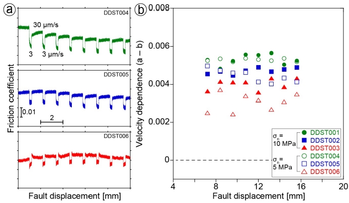
(a) Close-up view of the results from the VS tests plotted in Fig. 4b from which friction-rate parameter (a – b) values were obtained. (b) Plot of a – b versus fault displacement at 5 and 10 MPa normal stresses. All the specimens show positive a – b values. Note that the saturated powder and wafer specimens show the highest and the lowest a – b values, respectively.
단층비지의 마찰회복 특성을 이해하기 위해 전단변위 19-26 mm 구간에서 SHS 실험을 실시하였다(그림 4, 6). 각각의 전단을 멈추는 시간에서 변화한 마찰계수(Δµ)를 측정하여(그림 6a) 기울기가 나타내는 마찰회복률을 구하였다(그림 6b). 실험 조건에 상관없이 모든 시료에서 거의 0에 가까운 매우 낮은 마찰회복률이 확인되지만(그림 6), 각각의 시료에서 약간의 차이가 나타났다. 수직응력 5 MPa하에서 실시한 실험에서 물로 포화된 분말 시료의 마찰회복률은 0.0007이고, 수직응력 10 MPa하에서 실시한 실험에서는 0.0015로 상대적으로 높은 범위를 보였다(그림 6a, DDST004). 반죽 시료의 경우 수직응력 5, 10 MPa에서 0.0004의 동일한 마찰회복률이 산출되었고, 전단을 멈춘 후 정지상태로 유지시킨 시간(hold time)이 길어짐에 따라 마찰계수가 감소하는 경향을 보인다(그림 6a, DDST005). 웨이퍼 시료의 마찰회복률은 수직응력 5 MPa하에서 -0.00002, 수직응력 10 MPa하에서 -0.0001로 세 시료 중 가장 낮고, 재전단 시 마찰회복이 발생하지 않는 음의 회복률을 보였으며, 재전단으로 인해 전단변위가 증가할수록 마찰계수가 감소하는 경향도 확인되었다(그림 6a, DDST006).
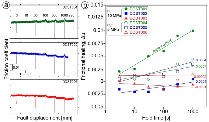
(a) Close-up view of the results from the SHS tests plotted in Fig. 4b. (b) Frictional healing (Δμ) plotted against hold time for the SHS tests performed at 5 and 10 MPa normal stresses. Solid straight lines are log-linear best-fit lines. The slopes of them are healing rates (β). The saturated powder and paste specimens show very small positive or nearly zero healing rates, whereas the wafer specimen shows a negative healing rate.
4. 토 의
이번 연구에서는 자연 상태 그대로(in-situ)의 특성, 특히 자연의 변형조직을 보유한 단층비지(intact fault gouge)의 마찰특성을 이해하기 위하여 새로운 시료채취기와 채취방법을 개발하였으며 이를 통해 단층비지의 웨이퍼 시료를 얻어냈다. 동일한 단층에서 채취한 단층비지로부터 (1) 물로 포화된 분말 시료, (2) 반죽 시료, (3) 웨이퍼 시료를 준비하여 전단실험을 실시한 결과, 물로 포화된 분말과 반죽 시료에서의 마찰계수는 기존에 보고된 단층비지의 값(Collettini et al., 2009; Tesei et al., 2012; Woo et al., 2016)과 유사한 0.3-0.4가, 웨이퍼 시료에서는 가장 낮은 ~0.25가 측정되었으며, 수직응력 10 MPa하에서보다 수직응력 5 MPa하에서 더 낮은 마찰계수가 관찰되었다. 이러한 결과는 웨이퍼 시료의 경우 자연 단층에서 발달한 변형조직(엽리 등)이 새로운 미끌림 시 효과적인 미끌림면으로 이용됨으로써 그러한 구조발달이 없는 상태에서 미끌림이 개시된 다른 시료들에 비해 더 낮은 전단응력 하에서 미끌릴 수 있음을 시사한다. 이는 이번 연구에서 사용한 웨이퍼 시료와 유사한 방식으로 자연 단층암 시료를 준비하여 전단실험을 실시한 기존 연구결과와도 부합한다(Collettini et al., 2009; Tesei et al., 2012).
마찰안정성 측면에서 볼 때, 모든 시료가 전단강도의 양의 속도의존성(즉, 속도가 증가하면 전단강도도 증가; a – b > 0)을 보이나, 분말과 반죽 시료에서보다 웨이퍼 시료에서 더 낮은 a – b값이 관찰된다. 양의 속도의존성은 그 물질이 본질적으로 안정한 미끌림(intrinsically stable sliding; Dieterich, 1979; Ruina, 1983; Marone, 1998a) 방식으로 거동할 것을 지시하나, 변형조직이 발달한 웨이퍼 시료에서 왜 더 낮은 a – b값을 가지게 되는지는 미구조 관찰과 함께 자세히 분석되어야 할 측면이다.
마찰회복률의 경우, 세 가지 유형의 시료 모두에서 거의 0에 가까운 값이 관찰된다. 이는 점토질 비지가 발달한 단층의 경우, 응력이 크게 축적되지 못하기 때문에 큰 지진을 동반하며 단층미끌림이 개시될 가능성은 작다는 것을 시사한다(Boulton et al., 2012; Carpenter et al., 2012; Tesei et al., 2012; Chen et al., 2015). 한편, 웨이퍼 시료의 경우 전단변위가 증가할수록 마찰회복률이 감소하는 경향을 보인다. 이러한 특성이 변형조직의 발달과 직접적인 관계가 있는지는 미구조 관찰을 통해 추가적으로 확인할 필요가 있다.
이상의 예비실험 결과들을 종합해보면, 자연의 변형조직을 보존한 시료의 경우 다른 유형의 시료와 구별되는 마찰특성을 가질 수 있는 것으로 보인다. 즉, 단층비지가 갖는 변형조직의 영향이 기존의 연구에서 확인된 단층의 전단강도 측면(Collettini et al., 2009) 뿐 아니라, 미끌림 방식 등 보다 다양한 측면에까지 작용할 수 있음을 시사한다. 따라서, 자연 단층의 미끌림을 실험연구를 통해 보다 과학적으로 모의하기 위해서는 수직응력, 미끌림 속도, 온도 등 미끌림 조건을 만족시키려는 노력뿐 아니라 자연의 단층 미끌림대의 물질 및 변형조직의 특성을 보존한 상태의 시료 준비에도 더 많은 노력이 요구된다고 하겠다.
Acknowledgments
이 논문은 2018년도 정부(과학기술정보통신부)의 재원으로 한국연구재단의 지원을 받아 수행된 연구(2016R1A2B4009599)의 결과입니다. 본 논문을 세심하게 심사하여 질적 향상에 도움을 주신 조형성 박사님과 익명의 심사위원께 감사드립니다. 단층암 시료 채취기의 제작에 큰 도움을 주신 성기성님과 전단실험에 도움을 주신 한국지질자원연구원 이희권 박사님께 감사를 표합니다.
References
-
Blanpied, M.L., Lockner, D.A., and Byerlee, J.D., (1992), An earthquake mechanism based on rapid sealing of faults, Nature, 358(6387), p574-576.
[https://doi.org/10.1038/358574a0]

-
Boulton, C., Carpenter, B.M., Toy, V., and Marone, C., (2012), Physical properties of surface outcrop cataclastic fault rocks, Alpine Fault, New Zealand, Geochemistry, Geophysics, Geosystems, 13, Q01018.
[https://doi.org/10.1029/2011GC003872]

-
Carpenter, B.M., Marone, C., and Saffer, D.M., (2009), Frictional Behavior of Materials in the 3D SAFOD Volume, Geophysical Research Letters, 36, L05302.
[https://doi.org/10.1029/2008GL036660]

-
Carpenter, B.M., Saffer, D.M., and Marone, C., (2012), Frictional properties and sliding stability of the San Andreas fault from deep drill core, Geology, 40, p759-762.
[https://doi.org/10.1130/g33007.1]

-
Chen, J., Verberne, B.A., and Spiers, C.J., (2015), Effects of healing on the seismogenic potential of carbonate fault rocks: experiments on samples from the Longmenshan Fault, Sichuan, China, Journal of Geophysical Research: Sodid Earth, 120, p5479-5506.
[https://doi.org/10.1002/2015JB012051]

-
Collettini, C., Niemeijer, A., Viti, C., and Marone, C., (2009), Fault zone fabric and fault weakness, Nature, 462, p907-910.
[https://doi.org/10.1038/nature08585]

-
Dieterich, J.H., (1979), Modeling of Rock Friction 1. Experimental Results and Constitutive Equations, Journal of Geophysical Research, 84, p2161-2168.
[https://doi.org/10.1029/JB084iB05p02161]

-
Faulkner, D.R., Jackson, C.A.L., Lunn, R.J., Schlische, R.W., Shipton, Z.K., Wibberley, C.A.J., and Withjack, M.O., (2010), A review of recent developments concerning the structure, mechanics and fluid flow properties of fault zones, Journal of Structural Geology, 32, p1557-1575.
[https://doi.org/10.1016/j.jsg.2010.06.009]

-
Faulkner, D.R., Lewis, A.C., and Rutter, E.H., (2003), On the internal structure and mechanics of large strike-slip fault zones: field observations of the Carboneras fault in southeastem Spain, Tectonophysics, 367, p235-251.
[https://doi.org/10.1016/S0040-1951(03)00134-3]

-
Haines, S.H., van der Pluijm, B.A., Ikari, M.J., Saffer, D.M., and Marone, C., (2009), Clay fabric intensity in natural and artificial fault gouges: Implications for brittle fault zone processes and sedimentary basin clay fabric evolution, Journal of Geophysical Research: Solid Earth, 114, B05406.
[https://doi.org/10.1029/2008JB005866]

-
Holdsworth, R.E., (2004), Weak Faults-Rotten Cores, Science, 303, p181-182.
[https://doi.org/10.1126/science.1092491]

-
Ikari, M.J., Marone, C., and Saffer, D.M., (2011), On the relation between fault strength and frictional stability, Geology, 39, p83-86.
[https://doi.org/10.1130/g31416.1]

-
Ikari, M.J., Saffer, D.M., and Marone, C., (2009), Frictional and hydrologic properties of clay-rich fault gouge, Journal of Geophysical Research: Solid Earth, 114, B05409.
[https://doi.org/10.1029/2008JB006089]

-
Kim, C.-M., Han, R., Jeong, G.Y., Jeong, J.O., and Son, M., (2016), Internal structure and materials of the Yangsan fault, Bogyeongsa area, Pohang, South Korea, Geosciences Journal, 20, p759-773.
[https://doi.org/10.1007/s12303-016-0019-8]

-
Marone, C., (1998a), Laboratory-derived friction laws and their application to seismic faulting, Annual Review of Earth and Planetary Sciences, 26, p643-696.
[https://doi.org/10.1146/annurev.earth.26.1.643]

-
Marone, C., (1998b), The effect of loading rate on static friction and the rate of fault healing during the earthquake cycle, Nature, 391, p69-72.
[https://doi.org/10.1038/34157]

-
Marone, C., Raleigh, C.B., and Scholz, C.H., (1990), Frictional Behavior and Constitutive Modeling of Simulated Fault Gouge, Journal of Geophysical Research, 95, p7007-7025.
[https://doi.org/10.1029/JB095iB05p07007]

-
Moore, D.E., and Lockner, D.A., (2011), Frictional strengths of talc-serpentine and talc‐quartz mixtures, Journal of Geophysical Research: Solid Earth, 116, B01403.
[https://doi.org/10.1029/2010JB007881]

-
Morrow, C.A., Radney, B., and Byerlee, J.D., (1992), Frictional strength and the effective pressure law of montmorillonite and illite clays, In: Evans, B., and Wong, T.-F. (Eds.), Fault Mechanics and Transport Properties of Rocks, Academic Press, p69-88.
[https://doi.org/10.1016/S0074-6142(08)62815-6]

-
Ruina, A., (1983), Slip Instability and State Variable Friction Laws, Journal of Geophysical Research: Solid Earth, 88, p10359-10370.
[https://doi.org/10.1029/JB088iB12p10359]

-
Saffer, D.M., and Marone, C., (2003), Comparison of smectite- and illite-rich gouge frictional properties: application to the updip limit of the seismogenic zone along subduction megathrusts, Earth and Planetary Science Letters, 215, p219-235.
[https://doi.org/10.1016/S0012-821X(03)00424-2]

-
Scuderi, M.M., and Collettini, C., (2016), The role of fluid pressure in induced vs. triggered seismicity: insights from rock deformation experiments on carbonates, Scientific Report, 6, 24852.
[https://doi.org/10.1038/srep24852]

-
Smith, S.A.F., Billi, A., Di Toro, G., and Spiess, R., (2011), Principal slip zones in limestone: microstructural characterization and implications for the seismic cycle (TreMonti Fault, Central Apennines, Italy), Pure and Applied Geophysics, 168, p2365-2393.
[https://doi.org/10.1007/s00024-011-0267-5]

-
Smith, S.A.F., and Faulkner, D.R., (2010), Laboratory measurements of the frictional properties of a natural low-angle normal fault: The Zuccale fault, Elba Island, Italy, Journal of Geophysical Research: Solid Earth, 115, B02407.
[https://doi.org/10.1029/2008JB006274]

-
Smith, S.A.F., Tesei, T., Scott, H.M., and Collettini, C., (2017), Reactivation of normal faults as high-angle reverse faults due to low frictional strength: Experimental data from the Moonlight Fault Zone, New Zealand, Journal of Structural Geology, 105, p34-43.
[https://doi.org/10.1016/j.jsg.2017.10.009]

-
Tesei, T., Collettini, C., Carpenter, B.M., Viti, C., and Marone, C., (2012), Frictional strength and healing behavior of phyllosilicate-rich faults, Journal of Geophysical Research: Solid Earth, 117, B09402.
[https://doi.org/10.1029/2012JB009204]

-
Woo, S., Han, R., Kim, C.-M., Jeong, G.Y., Jeong, J.O., and Lee, H., (2016), Relation between temporal change of fault rock materials and mechanical properties, Journal of the Geological Society of Korea, 52, p847-861, (in Korean with English abstract).
[https://doi.org/10.14770/jgsk.2016.52.6.847]

-
Woo, S., Lee, H., Han, R., Chon, C.-M., Son, M., and Song, I., (2015), Frictional properties of gouges collected from the Yangsan Fault, SE Korea, Journal of the Geological Society of Korea, 51, p569-584, (in Korean with English abstract).
[https://doi.org/10.14770/jgsk.2015.51.6.569]
